This thread has been locked.

If you have a related question, please click the "Ask a related question" button in the top right corner. The newly created question will be automatically linked to this question.

ISOM8110: CTR at low VCE condition

Part Number: ISOM8110

Tool/software:

Hi team,

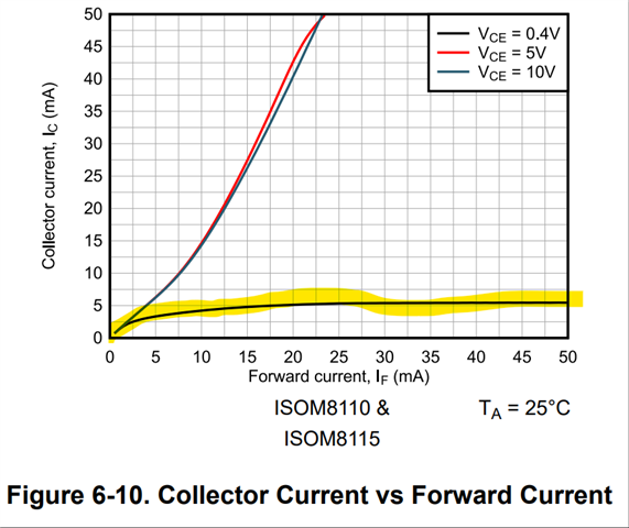
My customer considers to use ISOM8110 as digital output usage(High/Low output).

The datasheet states at VCE=0.4V, Ic is saturated to about 5mA regardless of If, so it appears there is not CTR virtually.

How should we consider device-device variation range and temperature dependency of the saturated value when the device is used as digital output?

Best regards,

Shota Mago

  • Hello Mago-san, 

    The ISOM8110 is not outputting a current at the collector in this condition. Typically, a resistor is used to limit the current from VCC into the collector. This resistor sets the current available to the isOM8110 output. 

    The output transistor will be in saturation mode as long as IF greater than the maximum IC set by the pull-up resistor

    Best,
    Andrew

  • Hi Andrew,

    Thanks for your reply. It makes sense.

    Just to make sure, graph of above Figure 6-10 at VCE=0.4V was tested with resistive load and the resistor limited current to about 5mA?

    While, at higher CTR model, saturated current value also increased.

    Best regards,

    Shota Mago

  • These graphs show the maximum collector current at which VCE does not go above 0.4 V. This is a typical value, so you'd have to design for a smaller current. With ISOM devices, the device and temperature variations are smaller than with optocouplers.

    If I were to design a circuit to transmit a digital signal, I would take inspiration from the test conditions in section 6.8 (IF = 1.6 mA, RL = 4.7 kΩ), but then look at figure 6-4 and increase IF to 5 mA to be safe.

  • Clemens,

    Thanks for your comment.

    Figure 6-4 is easier to understand characteristics of CTR vs VCE. 

    Best regards,

    Shota Mago