This thread has been locked.

If you have a related question, please click the "Ask a related question" button in the top right corner. The newly created question will be automatically linked to this question.

ISOM8113: Ton / Toff times

Part Number: ISOM8113

Tool/software:

Hi, 

Please could you provide some guidance on the Ton/Toff times: 

1) How are these likely to vary with temperature - it's only listed at RTP. 

2) Is there no Min/Max listed because it's circuit dependent? Is there anyway to approximate what this might be for our design? We have Vcc=3.3V, Rl=3.3k, If=1.5mA. CL is unknown but as it's connecting to an SN74LVC2G14DBVR which lists 4pF and we have a relatively short trace, we're assuming it's lower than 50pF. 

Many thanks

  • Hello, please allow some additional time for a response. I am checking to see what data we have with respect to temperature variance 

  • Hello Pjs, 

    1. Figure 6-29. Switching Time vs Ambient Temperature would be the most relevant to your test conditions.
    2. Correct, there is no min/max because it is circuit dependent. The trend for load resistance should follow be fairly similar since 3.3k and the test resistance 4.7k are close (seen in Figure 6-25. Switching Time vs Load Resistance). 
      1. The 50pF capacitance is meant to estimate common trace/bus capacitance and therefore should not affect the measurement too much. 

    Best,
    Andrew

  • Hi Andrew, 

    Thank you very much for this and for pointing out the figure. It's useful to see the Ton/Toff declines with increased temperature. 

    Is there any guidance of how the Ton/Toff will vary across batch from device to device?

    Also am I right in understanding that because tS (storange) time is listed as a maximum of 21uS @ 25C (and presumably improves with ambient based on figure 6-29) can I assume that our absolute worst case tOFF is (21us+Tr) as per figure 7-3?

    Are there any similar devices that have a much improved Tstorage time? We would like a faster response if possible.

    Many thanks

  • Please could you also tell me the carrier frequency?

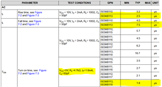
  • My apologies - one further question. I notice that the Ton should encapsulate the Tfall time as denoted in Figure 7-3. However, the Ton time is listed for a 5V 4.7kR If=1.6mA as 1.8uS as below. This is shorter than the listed fall time of 2.5uS? I assume this is again to do with the circuit loading but we need some guidance to understand how to properly determine these timings for our design.

  • Hello Pjs, 

    can I assume that our absolute worst case tOFF is (21us+Tr) as per figure 7-3?

    Yes, TOFF = Ts + Tr according to figure 7-3. However, you can use the worst-case typical value for a given typical application curve to get a better value for your test case. 

    Please note that the Tr 

    Please could you also tell me the carrier frequency?

    Unfortunately, I cannot share this information publicly at this time. Let me know if there is a specific frequency band that you are concerned about. 

    This is shorter than the listed fall time of 2.5uS? I assume this is again to do with the circuit loading but we need some guidance to understand how to properly determine these timings for our design.

    After a quick discussion with our team members, I realized this is a not as straight forward. We need to pay attention to the test conditions to make sure the output transistor is in saturation mode (being used as a switch).

    • Saturation mode (when ISOM is acting as switch) is achieved when IF * CTR >>IC_max.
      • Saturation mode specs are shown in Ton, Toff, and Ts when the test condition starts with VCC=5V. 
      • You will notice two conditions are provided to show the device in saturation mode with a strong IF (16mA) and a weaker IF (1.6mA). The typical application curves usually use the 1.6mA test condition. 
    • The ISOM811x is in active mode (analog behavior) when IC_max > IF *CTR.
      • Active mode specs for tr, tf, Ton, Toff can be identified when the test condition starts with VCC=10V. 

    Please use the saturation mode specs when calculating the timing parameters. 

    Best,
    Andrew

  • Hi Andrew, 

    Thank you for your reply. 

    Does this mean that the saturation timings are the worst case and non-saturated timings are faster? This is surprising as you'd assume the rise/fall would be sharper with more current on the LED side. Our input current is closer to 1.5mA. In this case, does this mean the worst case of 21uS is very unlikely?

    Many thanks

  • Hi, 

    Yes, the worst case Ts is unlikely. Keep in mind that Ts (max) is included in the TOFF measurement (figure 7-3), and the provided TOFF is a typical value. 

    The data sheet shows saturated mode will have faster switching performance when compared to unsaturated (with the specs where IF = 16mA are even faster). The red boxes are the non-saturated timings. TON + TOFF together here is 19.4us which is slower than the saturated (at 1.6mA) TON + TOFF which is 15.3us. Therefore, the saturated performance is faster. 


    Best,
    Andrew