A related question is a question created from another question. When the related question is created, it will be automatically linked to the original question.
If you have a related question, please click the "Ask a related question" button in the top right corner. The newly created question will be automatically linked to this question.
[FAQ]: What is Radiated Immunity per IEC 61000-4-3?
*Please note that all definitions and references are based on the latest standard IEC 61000-4-3
Radiated Immunity (RI)
Definition:
RI is a devices ability to withstand strong electromagnetic fields (EMF) from external systems such as radios and/or other EMF emitting devices. RI testing exposes a device/s to radio frequency EMF and its standard is defined by IEC 61000-4-3 which states the equipment, setup, procedure, and format of the results.
Why is radiated immunity important in isolated systems?
It is required that the isolator is able to maintain operation without any major degradation of performance in the presence of electromagnetic radiation (EMR). An inability to properly withstand EMR can cause electrical currents and voltages to couple into the isolator and lower system performance.
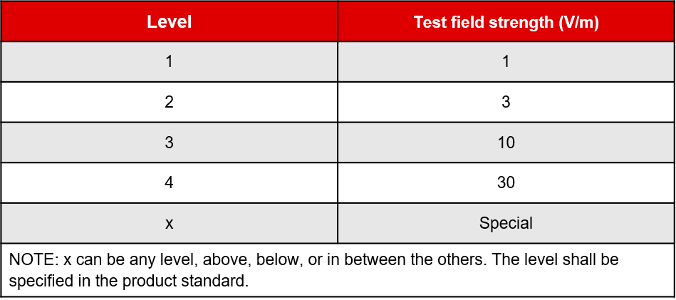
Test level
The radiated immunity test is conducted at one of the levels above with the option of adding additional levels above, below, or in between the others. Level 1 represents the lowest test level with a field strength of 1V/m while level 4 represents the highest with a field strength of 30V/m. At a given test level, the test is conducted across a frequency range determined by the manufacturer. At TI, we test at low frequencies (80MHz – 1GHz) and high frequencies (1GHz – 6GHz).
Test equipment
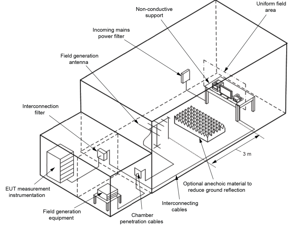
Example of test facility
The following equipment is used in the test setup and procedure:
Anechoic chamber
EMI filters
RF signal generator
Power amplifiers (to amplify signal)
Field generating antennas (i.e. biconical, horn, log periodic etc.)
Isotropic field sensor
Power measurement device for forward power
Associated equipment to record the power levels
An example of a semi-anechoic chamber (SAC) is represented in the picture below in the test setup & procedure section. To reduce EMF reflection, this chamber has anechoic material around the entire room (excluding the floors).
Test setup & procedure
The DUT is placed on a non-conductive table within the uniform field area at a height of 0.8(±0.05)m. The antenna is set 3m away from the DUT with a piece of anechoic material separating the two. This setup can be seen below.
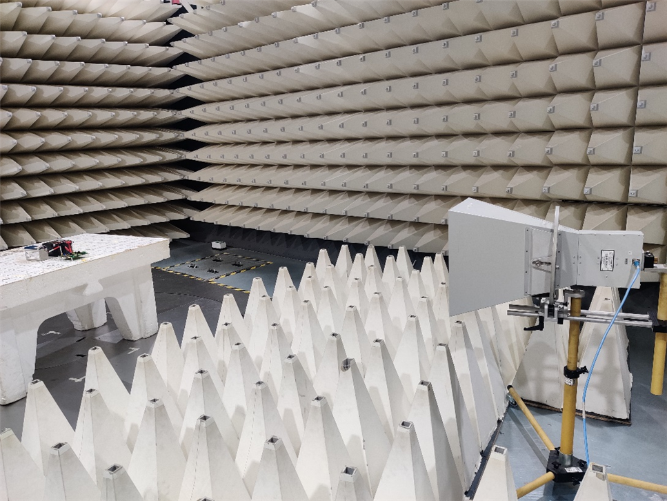
Setup for (1GHz – 6GHz) Test with Horn Antenna
The test is conducted at a test level, frequency range, and test modulation. The frequency range is swept with a type of signal modulation, and the test is only paused to adjust RF signal level, switch oscillators/antennas, or the tested frequency range.
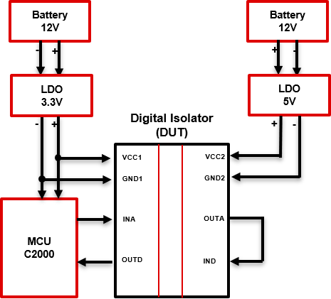
Example schematic of ISOxxxx under test:
Test Results
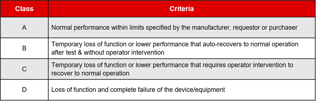
The test results are evaluated by classifications of function loss or part degradation, and performance level defined under test levels section above. The classification of function loss or part degradation are tabulated below:
The overall test results are listed as:
ISOxxxx passes level 4 for (1GHz – 6GHz) at criteria A
or…
ISOxxxx passes 30V/m for (1GHz – 6GHz) at criteria A
Which means, ISOxxxx withstood a test field of 30V/m for frequencies between (1GHz – 6GHz) without any loss of function or degradation of performance.