A related question is a question created from another question. When the related question is created, it will be automatically linked to the original question.
If you have a related question, please click the "Ask a related question" button in the top right corner. The newly created question will be automatically linked to this question.
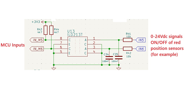
ISOM8110 is functionally equivalent ILD213T and should be able to drop into the schematic without major changes. Please note that the ISOM8110 is currently only a single channel device, therefore the footprint may need to be changed.
Thanks so much Andrew, any Application note with typical connections (or recommended values) to work as switching & input filter (RC, ...)? (no need inputs with high speed)
The filter's cut off value needed for your design will depend on your application requirements. The current filter's cutoff frequency is ~160Hz = 1/(2*pi*10k*100n). This filter selection is okay. The same filter will work for ISOM8110 since it is a functional match for the current design. Please note that faster data rates may be possible since ISOM8110 has a faster isolation technology (BW = 680kHz).
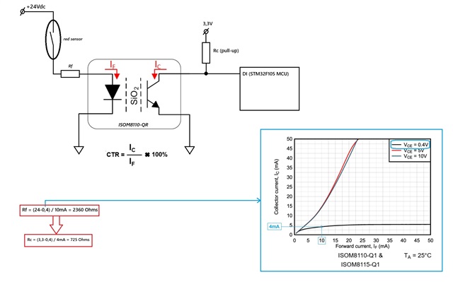
Sorry, but is a little confuse for me understand the swithing mode of ISOM8110/1. I find it difficult to understand the relationship between a sufficiently high IF, so that the output transistor works saturated (small VCE), for specific conditions of a 'pull-up' resistor connected to 3V3 (input of my MCU). Could you help me ¿?
Is this hypothesis presented in the image correct?
The ISOM811x will be in saturation mode whenever the collector current is limited below the IF*CTR, or IF*CTR > IC. This is shown in the figure where VCE = 0.4V.
The equations you showed are mostly correct.
RF = (VCC - VF) / IF = (24V-1.4V)/10mA = 2260ohms
Rc is correct. However, please note that 4mA limit is set by the pull up resistor. (VCC=5V, RL=4.7kΩ; which corresponds to the Ic=1mA test condition for VCE)