ISOW1432: ISOW1432

Part Number: ISOW1432

Tool/software:

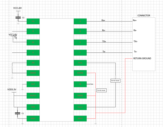
I want to select an isolated RS422 chip with a data rate of 10 Mbps or higher. It doesn't need a separate ISO power supply. The ISOW1432 seems to be a suitable choice. However, there are only two IO pins reserved on the front-end board, which are used to control R and D respectively. RE and DE are prepared to be directly connected to fixed voltage levels. But I saw on a forum today that this connection method may cause the chip to overheat when there is no communication externally. I would like to know if there are any other ways to improve this situation? Or are there any other models you can recommend? Thank you.

  • Hi Yang,

    Thanks for reaching out.

    DE being always high will surely result in excess current consumption during no communication since drivers will drive the external load. Even ISOW1432 datasheet supply current numbers indicate the same. 

    One Suggestion that I have is shorting RE and DE, and toggle it based on Transmit and Receive operation.

    Apart from that I don't have any further suggestion for you.

    Regards
    Varun

  • I understand that this has become a half-duplex working mode, while we expect it to be in full-duplex mode. If we connect DE and /RE according to our design to keep them always enabled, will the chip overheat and get damaged when there is no external communication? Can adding a heat dissipation device improve the situation? Or can I add another control pin to control EN/FLT? Thank you.

  • Hi Yang,

    I don't see the device getting overheat till its damaging point.

    However, to be sure let me know - What is your VDD and VISOOUT requirement. Also, the max operating temperature?

    Regards
    Varun

  • Hi,

    The board operates in an environment of 0 - 50 degrees, with VDD at 3.3V and VISOOUT at 0V, and the IO voltage is 1.8V. What we expect is that no external power supply is required.

  • Hi Yang,

    The temperature range is absolutely safe to operate ISOW1432 with your RE/DE configuration.

    Based on your last reply, I have a different question - what do you mean by this 

    VISOOUT at 0V, and the IO voltage is 1.8V. What we expect is that no external power supply is required.

    With VDD(Pin9) =3.3V, VISOOUT(Pin12) will be 3.3V, and VISOOUT(Pin12) needs to be shorted to VISOIN(Pin16), or else the ISOW1432 will not be functional. No concerns with VIO being 1.8V.

    Please read the datasheet thoroughly before designing the system.

    Regards
    Varun

  • Hi,

    I think there may be some misunderstandings. What I mean is that the Vout voltage at the connector doesn't need to output or input. Customers only need to connect TX+/ - and RX+/ -. I roughly drew a simple application diagram. Could you please take a look and tell me if there are any risks such as overheating when it operates in an environment of 0 - 50 degrees? Thank you.

  • Hi Yang,

    I've already clarified on 0-50 degrees operation above - it is safe to go ahead.

    The Block Diagram is also good except the RETURN GROUND connection should be to GISOIN and GISOOUT.

    For Detailed connection details, please refer datasheet layout diagrams and follow them strictly and you can refer ISOW1432 EVM as a reference design as well.

    Regards
    Varun