ISO3082: RS485 Hub Over RJ45 Jack

Part Number: ISO3082
Other Parts Discussed in Thread: THVD1505,

I'm working on a industrial electronics project, and I want to use RS485 modbus to communicate between nodes.

One idea was to use RJ45 jacks and CAT6e cable to deliver RS485 and power to each slave. There are two possible configurations:

1) A daisy chain where power and data are passed from one slave to another.  In this case, the limiting factor is the voltage drop along the whole string.

2) Have all RJ45 ports on the master, with the data lines passing back-and-forth between the master and slave.  I would use two twisted pairs in the CAT6e: one from master --> slave and another from slave --> master.  This way, power is provided to each slave individually and voltage drop is minimized.  

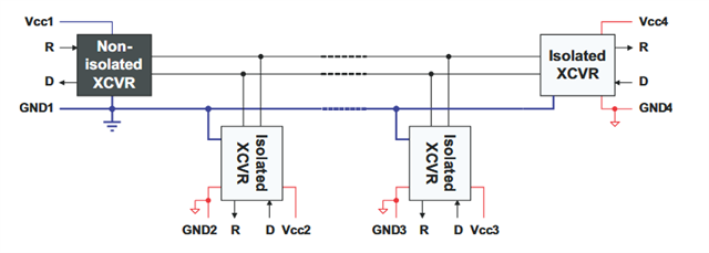
The hub would have a single isolated transceiver, and the slaves would be powered over the field 24V. The topology would still be linear, the stubs would just be the length of diff pair between the RJ45 port and the transceiver. Power and ground would look like a star topology.

If using less than 8 slaves, I would have a small board with a 100 ohm termination resistor. Each slave will be connected with no more than 10m of cable.

Some slaves will not be isolated, and use THVD1505 as a transceiver.  

Here's an album with what I was thinking.

With a more standard daisy chain, and without power supplied from the local installation, there can be enough voltage drop along the network and violate the common mode voltage range of the transceiver.

Another concern I had is about powering the slave devices from the field.  

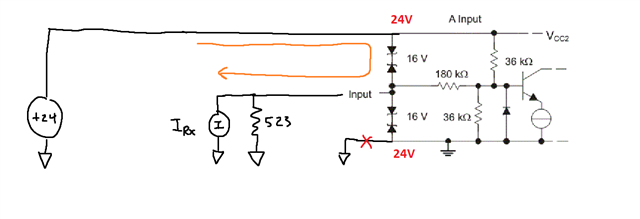
The TI RS-485 guide shows the ideal network with isolated transceivers and power provided across the isolation gap.  My network would be powered from the field, and the slave is not isolated. What happens when hot-plugging the devices, or if the ground connection is lost? 24V would be way above the common mode input limit of the transceiver, and then the protection diodes on the input will find their own ground through the data lines.  This may happen randomly, as some contacts make contact before others. 

The THVD24x0 is fault tolerant to +/-70V, but it seems from the datasheet that the fault currents are only limited for the receiver.  Does this mean, with a missing ground, that the slaves could power through the driver?  

How should hot-plugging devices be handled when power is supplied from the field?

  • Hello,

    Thanks for reaching out.

    Please give us a few extra days to get back due to the Holidays.

    Regards,
    Aaditya

  • Hello Robert, 

    Thank you for your question. There is a lot of discussion here, so I have copied your questions below: 

    1.  My network would be powered from the field, and the slave is not isolated. What happens when hot plugging the devices, or if the ground connection is lost?
      1. The transceivers will wake up in an idle state as long as the DE and RE/ are disabled on the isolated side. There will be no disturbance to the data if a device is added or removed (hot-plugged) while the network is transmitting data and the driver (DE) is disabled.
      2. A field side node will not be powered until both VCC2 and GND2 are connected. There should not be an error in transmission due to a plugging event. 
    2. Does this mean, with a missing ground, that the slaves could power through the driver?
      1. With a disconnected GND2 the slaves should not be powered through the A, B, X, Y lines. 
    3. How should hot-plugging devices be handled when power is supplied from the field?
      1. It is best practice to keep DE and RE/ both disables until the MCU node (VCC1) is completely connected and powered. 

    Best,
    Andrew

  • Hey Andrew,

    I appreciate the help, and apologies that the questions are a bit over the place.  I have some follow ups:

    •  My network would be powered from the field, and the slave is not isolated. What happens when hot plugging the devices, or if the ground connection is lost?
      1. The transceivers will wake up in an idle state as long as the DE and RE/ are disabled on the isolated side. There will be no disturbance to the data if a device is added or removed (hot-plugged) while the network is transmitting data and the driver (DE) is disabled.
        Yes, this makes sense to me.  I have both DE/RE pulled to off state by default.  However, even if the receivers are not enabled on power-up, there may be other transceivers on the bus with RE enabled.  It seems like most TI receivers consume ~100 uA - does this mean, with enough enabled receivers on the bus, slaves w/ missing ground can find a path to ground through the remaining enabled receivers on the bus?  This is assuming the input protection diodes will become reverse biased with a floating ground, and VCC becoming 24V. 
      2. A field side node will not be powered until both VCC2 and GND2 are connected. There should not be an error in transmission due to a plugging event. 
    • Does this mean, with a missing ground, that the slaves could power through the driver?
      1. With a disconnected GND2 the slaves should not be powered through the A, B, X, Y lines.
         Is this true for all TI transceivers, or only parts with an extended fault voltage range?  

        Not all parts disclose their input structure, but taking ISO3082 as an example, I would imagine when VCC floats to 24V that the protection diodes can breakdown, and the slaves may find ground through the bias resistors on the master or through the input bias current of the other receivers on the bus.


        Bus voltage on the slave side is supplied through a buck converter.  With missing ground, all outputs will float to the input voltage.

    • How should hot-plugging devices be handled when power is supplied from the field?
      1. It is best practice to keep DE and RE/ both disables until the MCU node (VCC1) is completely connected and powered. 
  • Hi Robert, 

    Thanks for the added details. Please allow me another day to review and get back to you. 

    Please note that the overvoltage tolerance only applies to the A, B, X, Y bus pins. The VCCx pins may not receive 24VDC as you have drawn since the internal protection's diodes are not designed for continuous current (VCCx abs max = 6V). 

    Best,
    Andrew

  • Yeah that's understood - in this case, both GND and Vcc will float to 24V.  I think this still respects the input voltage limit for VCC, since it is referenced to the (floating) ground.  Once ground is restored, Vcc will be regulated to 5V.  I can add a protection zener to ensure that when the 24V --> 5V power supply starts, VCC maximum is respected.  

  • Hello Robert, 

    If the GND and VCC are both at the same voltage, then this is okay. The absolute maximum condition is 6V with respect to the local GND. Any DC fault condition on the input bus pins would then be discharged through the ESD structures (in reverse of your arrow). This will be ignored on the isolated side if RE/ is disabled. 

    Best,
    Andrew