This thread has been locked.

If you have a related question, please click the "Ask a related question" button in the top right corner. The newly created question will be automatically linked to this question.

SN6507-Q1: Current calculation

Part Number: SN6507-Q1
Other Parts Discussed in Thread: SN6507

Hi Team,

Posting on behalf of our customer.

I will share this E2E post to our customer so he can reply when needed.

Currently, our  project uses TI’s SN6507+SM91208L. 

1、We need to evaluate the currents flowing through the SN6507 SW1&SW2 switch drive currents when driving the transformer.The current specified in the datasheet currently does not include the drive current. Please help assess how to evaluate it

2. Please provide the current calculation formulas for SW1 and SW2, along with the meanings of the variables. Also, please help calculate the current for our product (designed for 12V input, 15V output; f=1MHz);

3. Please provide your internal current test results, current waveform diagram, and calculations for the SN6507 chip;

4. Is the input current of the SN6507 related to the current at the output load? 

Regards,

Danilo

  • Hi Danilo,

    I will test the EVM and provide you the current test result.

    Thanks

    Prateek

  • Hi Danilo,

    Please find below input.

    1. How the switch node current looks like is mentioned in the datasheet in Figure 8-4. I have attached a Screenshot of that below. The switch node current would depend on the load connected at the output.

    2. The formula to calculate SW node current is very well explained in this video. 

         https://www.youtube.com/watch?v=kT1gvTmK1TE&list=PLGjyOARIhfLpjA6PoM7B65sd8cdEqJQWv&index=4

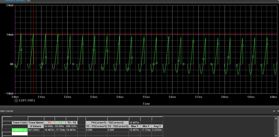
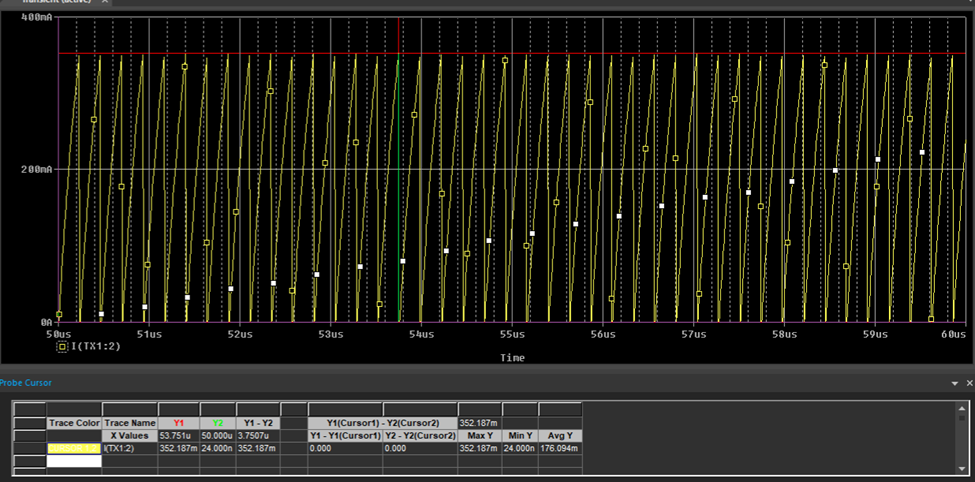
    3. Below is the switch node current waveform at SW1(ch3) and SW2(ch4).

    4. Yes the input current of SN6507 is related to the current at the output load and is directly proportional to it.

    Pls let me know if you any questions.

    Thanks,

    Prateek

  • Hello as we cannot access to Youtube easily in China, is there any other source of the vedio available?

       https://www.youtube.com/watch?v=kT1gvTmK1TE&list=PLGjyOARIhfLpjA6PoM7B65sd8cdEqJQWv&index=4

  • and could you help to directly calculate the current for our product (designed for 12V input, 15V output; f=1MHz)?

  • Hi Panwei,

    I can send the video to you over email. let me know your mail -id.

    Current at SW would depend upon transformer turns ratio and its magnetizing inductance. Which transformer are you using ?

    Thanks,

    Prateek

  • panwei.lv@forvia.com and also to our HW: jie.he@forvia.com

  • For detailed current calculations, I hope you can provide examples using formulas based on the parameters I provide, showing the SW node current under no-load and 150mA load conditions.

  • We are using SN6507+SM91208L_E

  • Hi Jie,

    Thanks for providing the details. I will update you as soon as I calculate the current at SW.

    Thanks,

    Prateek

  • Hello, has the calculation been completed? How long will it take to receive the results?Hello, has the calculation been completed? How long will it take to receive the results?

  • Hi Jie,

    Please find the below sources for detailed calculation of Current waveforms at SW.

    1. Chapter 14 in this handbook - https://www.ti.com/lit/eb/slyu036a/slyu036a.pdf?ts=1772520506279 

    2. You can also use https://www.ti.com/tool/POWERSTAGE-DESIGNER   to calculate values directly and see waveforms

    Thanks,

    Prateek

  • Hello, Please help me answer the following questions.

    1、I don't quite understand the formulas in the PDF. Could you please provide a detailed formula for calculating the SW node current and help me calculate the SW node current under no-load and 150mA load conditions based on the circuit parameters I provided?

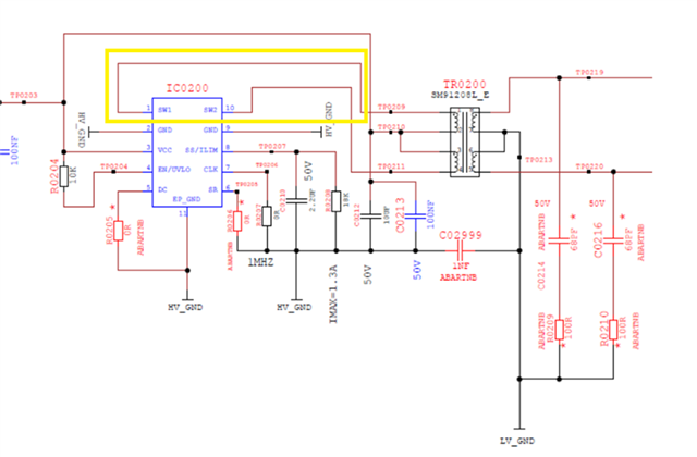
    2、Circuit application: SN6507 + SM91208L_E are used; input voltage 12V, output voltage 15V. The above are my circuit design requirements and parameters. Since I need to calculate the input current, please help me derive and calculate the input current in detail using the formula when the output current is 0A and 150mA (derivation process and calculation values ​​are required).The yellow section below is the current I need you to calculate.

    3.What is the relationship between the center tap current (marked in yellow) and the currents of switches SW1 and SW2? Is the center tap current (marked in yellow) equal to the sum of the currents of SW1 and SW2? How are the currents of SW1 and SW2 calculated? Please provide the formulas for calculating the currents of SW1 and SW2, as well as detailed calculated values for SW1 and SW2 when the output currents are 0A and 150mA respectively (the derivation and calculated values should be based on my circuit parameters).

    4.Below are my detailed schematics. Components marked in red are unmounted. Please help calculate the SW current based on the schematics and application requirements I provided.

  • Hi Jie,

    Give me two days, I'll get back to you with the calculation

    Thanks,

    Prateek

  • Hi Jie,

    Thanks for your patience. Pls find the formulas to calculate SW node current and simulation results with values.

    Formulas:

          avg(Issw2) = avg(Issw1) = Iout/2

          Ipsw1 = Issw1*(ns/np)

          Ipsw2 = Issw2*(ns/np)

          Input Current at primary center tap pin, Iin = avg(Ipsw1) + avg(Ipsw2)

         Issw1:- current at secondary side switch node 1

         Issw2:- current at secondary side switch node 2

         Ipsw1:- current at primary side switch node 1

         Ipsw2:- current at primary side switch node 2

         Iout = load current

         Iin = input current

    I performed the simulation (12V -> 15V) with SM91208L-E at no load and 150mA. Please find the results below.

    1) at no load

    i.  primary current at SW1, Iavg1 = 2.19mA

    ii. primary current at SW2, Iavg2 = 1mA

    iii. primary side current at center tap pin of transformer Iin =  Iavg1+Iavg2 = 3.19mA  

    2) at 150mA load

    i. primary current at SW1, Iavg1 = 90mA

    ii. primary current at SW2, Iavg2 = 90mA

    iii. primary side current at center tap pin of transformer Iin= Iavg1 + Iavg2 = 180mA


    You can also check it by doing the Pspice simulation 

    Pspice file of SN6507 - 

    Let me know if you have further questions

    Thanks and regards,

    Prateek Verma

  • 1. According to the formulas you provided, under a 0mA load condition:

    Primary current at SW1, Iavg1 = Issw1*(ns/np)=0*1.25=0mA

    Primary current at SW2, Iavg2 = Issw2*(ns/np)=0*1.25=0mA

    Primary side current at center tap pin of transformer Iin = Iavg1+Iavg2 = 0mA

    Although there is no load current, the push-pull mechanism is constantly working, and SW is always outputting. Theoretically, there should be current in this circuit, but this current is not zero. Please explain what formula can be used to derive this current?

    2. According to the formula you provided, under a 150mA load:

    avg(Issw2) = avg(Issw1) = Iout/2 = 150/2 = 75mA

    Primary current at SW1, Iavg1 = Issw1*(ns/np) = 75*1.25 = 93.75mA

    Primary current at SW2, Iavg2 = Issw2*(ns/np) = 0*1.25 = 93.75mA

    Primary side current at center tap pin of transformer Iin = Iavg1 + Iavg2 = 187.5mA Is this calculation correct?

    3.The values ​​you provided are simulation data. I would appreciate it if you could use the formula to calculate the theoretical values. I would also appreciate it if you could compare your calculated values ​​with the values ​​I calculated using the formula you provided, to see if my calculations are correct.

  • Hi Jie,

    Your calculation for 150mA load is correct. you can also see the simulated current values almost matches with the theoretical values.

    Please note that when there is no load at the output, the current that that we see at Switch nodes is magnetizing current, which can be calculated using below formula

    Ipri,max = Imag/2

    here Lp is primary inductance of transformer, t1 is FET on time. and Vf is diode forward voltage (i have assumed it to be 0.8V)

    Taking Fsw = 2MHz, you will get  Ipri,max = 12mA (as shown in simulation at no load)

    for Fsw = 1Mhz , Ipri,max = 24mA

    Then you can calculate the rms value and avg value from waveform at switchnodes.

    Thanks,

    Prateek

  • Hi Prateek,

    Customer cannot reply due to system issue, I attach below onbehalf of Jie. Please support. Thank you.

    hello

    Magnetizing current calculation:

    n = Ns/Np = 10/8 = 1.25

    Vin = 12V

    Vout = 15V

    Vf(typ) = 0.4V

    fsw = 1000000Hz

    LP = 130Uh (Is this the overall transformer inductance?)

    t1 = 1/(2*fsw) * (Vout+Vf)/(Vin*ns/np) = 1/(2*1000000) * (15+0.4)/(12*1.25) = 0.513us

    Imag = Vin*t1/LP = 12*0.513/130 = 0.0474A


    1. What does Imag mean?
    2. What does Ipri,max mean? Is it the maximum positive value?
    3. We need to calculate the average value. The waveform is a triangular wave. Is the average value Ipri,max/3?
    4. Is the calculation of the magnetizing current related to the duty cycle of the SW switch?
    5. Are my calculations above correct?
    6. When the load is 150mA, is it necessary to add a magnetizing current to the center tap current?


  • Please help me answer this, thank you.

  • Hi Jie,

    Please read this handbook - https://www.ti.com/lit/eb/slyu036a/slyu036a.pdf?ts=1772520506279

    It has all the formula you need and has been explained with the waveforms as well.

    1. Imag (Magnetizing current) is the small (2–5% of full load) current drawn by a transformer's primary winding to create the core's magnetic flux, even when no load is connected.

    2. Please see section - "14.1.1. Continuous Conduction Mode" page no. 124 in above handbook

    3. For avg and rms formula pls see section - "2.2. Positive triangular waveforms with offset" page no. 8

    4. Yes it is dependent on the duty cycle

    5. Your calculation are correct

    6. Yes you will need to add magnetizing current.

    Thanks, 

    Prateek

  • hello Prateek

    Reply onbehalf of jie

    Below are my calculations for the input center tap current under no-load and 150mA load conditions. Please double-check that they are correct. Thank you.


    1Output load is 0mA. Input magnetizing current calculation:

    n = Ns/Np = 10/8 = 1.25
    Vin = 12V
    Vout = 15V
    Vf(typ) = 0.4V
    fsw = 1000000Hz
    LP = 130uH
    t1 = 1/(2*fsw) * (Vout + Vf)/(Vin*ns/np) = 1/(2*1000000) * (15 + 0.4)/(12*1.25) = 0.513us
    Imag = Vin*t1/LP = 12*0.513/130 = 0.0474A
    Center tap Primary Current: Ipri = 1/2 * Imag = 0.0237A


    2With an output current of 150mA and a load, the input center tap current is calculated as follows:

    avg(Issw2) = avg(Issw1) = Iout/2 = 150/2 = 75mA

    Primary current at SW1, Iavg1 = Issw1*(ns/np) = 75*1.25 = 93.75mA

    Primary current at SW2, Iavg2 = Issw2*(ns/np) = 0*1.25 = 93.75mA

    Primary side current at the center tap pin of the transformer: Iin = Iavg1 + Iavg2 = 187.5mA

    Center tap Primary Current: I = Iin + Ipri = 187.5 + 23.7 = 211.2mA

  • hello   and Prateek

          Please reply to this, thank you.

  • Hi Jie,

    I have checked your calculation, they are correct.

  • hello Prateek

       Thank you for your support