Part Number: SN6507
Hi Team,
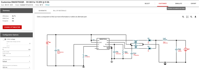
I'm unable to perform the simulation for the SN6507DGQRQ. Could you please provide any available simulation files or support (Webench, TINA, or PSpice)?
Regards,
Rami Reddy
Part Number: SN6507
Hi Team,
I'm unable to perform the simulation for the SN6507DGQRQ. Could you please provide any available simulation files or support (Webench, TINA, or PSpice)?
Regards,
Rami Reddy