This thread has been locked.

If you have a related question, please click the "Ask a related question" button in the top right corner. The newly created question will be automatically linked to this question.

ISO1212: ISO1212 bidirectional input design

Part Number: ISO1212

As the datasheet mentioned diagram as below, image.png

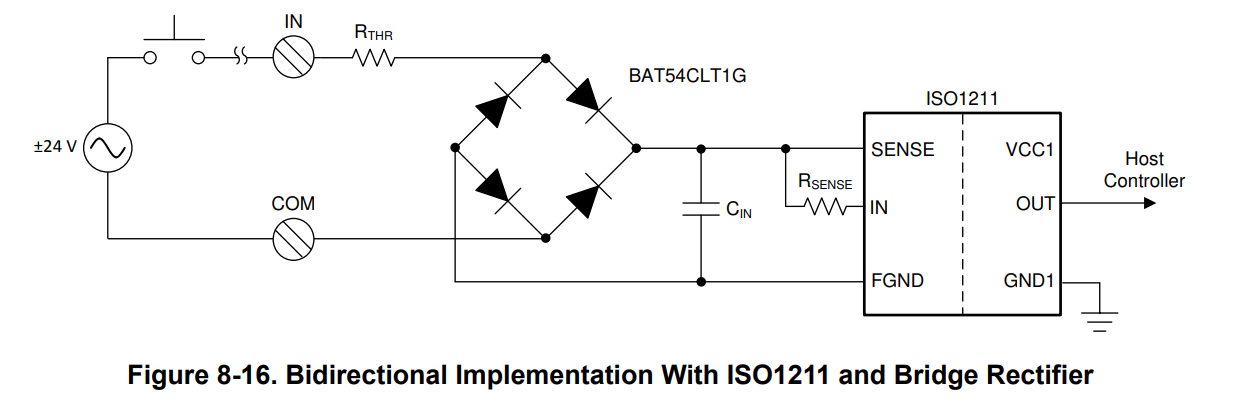
First: What the Cin position is better? Refer to the figure 8-16,  I think the Cin is design for filter then why not put the Cin after Rthr? What other purpose does it have?

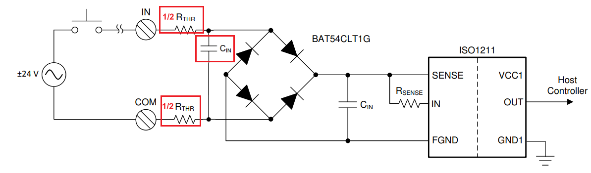
Second: Continuing the question1, reference circuit as below.

As the mentioned, we need a bidirectional input design, then filter also needed for two inputs so does Rthr can be divide by 2 then put at input side?    


image.png

Third, If we also need a TVS to prevent EMS , we can put it at where?


  • Hello Jensen,

    Thank you for reaching out. These are very good questions

    1. You are correct that the CIn is designed as a filter. For AC inputs, it should come after the rectifier to further smooth the rectified DC into a cleaner DC signal. Ciin makes sure that the rectified DC does not drop below the input threshold. It improves the quality and performance of the digital input signal.
      1. The circuit for AC inputs is essentially the same as a full-bridge rectifier. Here is a good demonstration.  
    2. You can divide Rthr and install as you have suggested. It is functionally the same as using a single Rthr. For surge performance, however, I believe there is some benefit to having a single surge-rated Rthr; however, I have not seen this tested. 
    3. The TVS diode can be placed before the Rthr; for best results, place it near the input terminals.  

    Best,
    Andrew

  • Hello Andrew,

    Thanks for your reply.

    For question 1, let me explain our application: we need a bidirectional design, in any given application, there will only one rectangle signal input. The input source maybe from the IN terminal or the COM terminal. Not the AC source shown in the picture. And I found a  use case for PLC, the capacitor of filter is placed at input side before rectifier. Maybe I could refer to this?  from Bidirectional Digital Input Figure 5. ISO1212 Input stage schematic

    2. Rthr has two two functions describe in datasheet, one is sets the voltage thresholds (VILand VIH) anothe is surge. If I divider resistor to two, it will affect the voltage thresholds? and considering prevent surge Shouldn't be more important that placed two resistors to the IN and COM side? Why you think that single resistor is better?

    Jensen

  • Hi Jensen, 

    Thanks for the explanation. I understand that your application is not looking for AC inputs and it needs to the ability to operate in the sink or source modes at 24Vdc. In this case the bridge rectifier design from Figure 5. ISO1212 Input Stage Schematic can be followed for your application. 

    1. The ISO121x will work with split/differential resistors. Dividing the resistor in two will not affect the voltage thresholds as long as both RTHRs add to the same value of the single RTHR in the datasheet.
      1. And you are correct; surge performance will not be affected as long as both resistors are equal pulse-proof resistors.
    2. The TVS diode typically comes after the RTHR. RTHR can be a surge-rated resistor that can help to improve the surge performance of the ISO121x. 
      1. The TVS diode can be placed in front of RTHR if a surge-rated resistor is not used.   
      2. In your application Cin is to help filter EMC as you suggested earlier. 
      3. Using a TVS eliminates the need of CIN for Transient Protection and enables faster system performance in terms of Bandwidth.

    Just so you are aware, we have the ISO1228EVM Evaluation board that can support both sink and source modes on the same BOM. In order to operate in both modes a parallel diode structure is used as shown in the datasheet graphic (box 1). 

    Best,
    Andrew