A related question is a question created from another question. When the related question is created, it will be automatically linked to the original question.
If you have a related question, please click the "Ask a related question" button in the top right corner. The newly created question will be automatically linked to this question.
Our wind power project uses your company’s ISO1050DUBR CAN isolator transceiver. Currently, one master device and six slave devices are connected to the same CAN bus. A 120Ω resistor is connected in parallel at the master device and the port of the sixth slave device, which is the farthest one. During waveform testing, we found that when multiple devices simultaneously send signals to the bus, the amplitude of the bus increases. What is the reason for this, and is it normal?
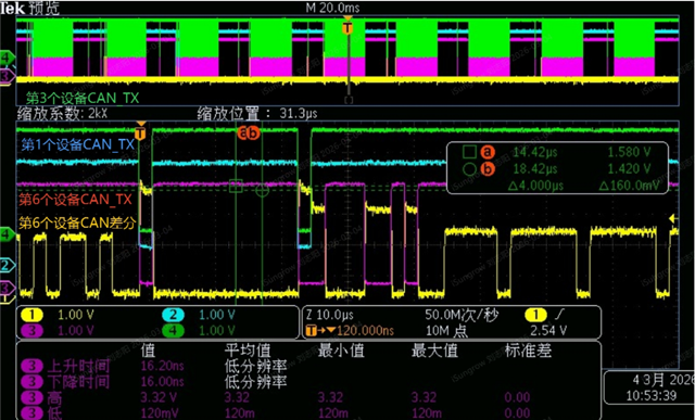
In the following figure, the green signal is the CAN_TX of the third device, the blue signal is the CAN_TX of the first device, the purple signal is the CAN_TX of the sixth device, and the yellow signal is the CAN differential signal of the sixth device.
Thank you for reaching out and including the scope captures.
Based on the waveform and your description, I see that there are multiple TXD nodes attempting to drive the bus. This is considered a "bus contention" fault since the CAN node that is receiving the message will not be able to differentiate which device is communicating as multiple nodes fight for control on the bus.
The increased amplitude shown on the CAN signal is common in bus contention cases since more than one node is driving the line dominant.
Please review your communication controllers to make sure each device has its own address and does not respond while other nodes are communicating.
The slave devices used for testing all have independent IP addresses. So, does the current situation indicate that there are some issues in my CAN communication loop, or is it a normal bus conflict that I don’t need to worry about?
Could you please help explain from the perspective of circuit principles why the voltage level increases during a conflict?
The current situation where multiple nodes drive TXD at the same time suggests some issue with the CAN communication loop. From my understanding, there is no reason for multiple nodes to drive a dominant (low TXD) to the CAN bus at the same time.
I can only comment on the behavior of ISO1050 (which looks to be expected here). I cannot safe if this a normal bus conflict for your system. Could multiple nodes be responding with a dominant to acknowledge the same error condition in your control loop?
The raised voltage level during bus conflict is the result of potential difference between nodes during the dominant state. The nodes on the bus are high impedance when the CAN bus is in the recessive state. When the single node switches to a dominant signal, the CANH and CANL pins drive the node to VCC2 and GND2 respectively using the output transistors.
When multiple nodes drive the bus, there is a mismatch between the local supply and ground at the original node and at a downstream node due to cabling losses.
The Change in CAN bus level is likely due to this mismatch.