This thread has been locked.

If you have a related question, please click the "Ask a related question" button in the top right corner. The newly created question will be automatically linked to this question.

ISOUSB211: Schematic Review

Part Number: ISOUSB211

Hi Team,

I'm planning to use the USB isolator ISOUSB211DPR in my board.

Please find the attached schematics and provide the feedbacks.

USB isolator ISOUSB211 updated.pdf 

Regards,

Abhishek

  • Hi Abhishek,

    Thanks for reaching out again for follow up review.

    This schematic has been reviewed multiple times and same comment has been provided again and again but unfortunately, I don't see the feedback being implemented.

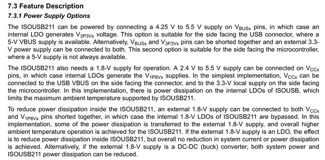
    First thing, the power supply configurations clearly descripted in datasheet needs to be understood:

    Based on these options - shorting VBUS1 and VCC1 does nto make any sense if you have option of connecting V1p8V1 externally because when connected externally the V1p8Vx and VCCx should be shorted together. Similarly if V3P3V is connected externally then, VBUS also needs to be shorted to V3P3V which I don;t see happening in the schematic.

    The above is only one of the gaps. However, please note that the supply capacitors look all good currently.

    Second, with the schematics given, it's not at all clear which supply is referenced to which ground since now you have two grounds - USB_GND and ISO_GND -> I see VCC_1V8 which is referenced to USB_GND on Side1 is getting connected to VCC2 as an option through 0ohm on Side2 while all the supply connections on Side2 is referenced to ISO_GND1

    There are multiple fundamental shortcomings like these here and there.


    As I've requested before, please refer ISOUSB211 EVM schematic for connections of supply options through 0ohm as wellISOUSB211DPEVM Isolated USB Evaluation Module. It has 0ohm options as well for different supply options as pert section 7.3.1 in datasheet which will help you in correcting the schematics quickly as well.

    But before that, I request you to please read the section 7.3.1(snap above) and understand how the supply should be connected for different possible scenarios - On this if you have any question, do let me know.

    Regards
    Varun

  • Hi Varun,

    Sorry for the inconvenience.

    For the USB connector side i have only 5V supply from the USB connector. As there must be separate ground reference on the both sides of the isolator, on USB connector side I can't provide 1V8 and 3V3 options, as for that i require again 2 regulators.

    As mentioned in the datasheet if the VBUS is supplied with 5V supply, internal LDO will generate the 3V3 and 1V8 voltages.

    For the MCU side of the isolator, VBUS i can connected to 3V3. Since VBUS is only 3V3 supply, VCC2 is also connected to the ISO_3V3 supply voltage. As in datasheet, if a 2.4V to 5.5V supply is connected to VCC2, then the internal LDO will generate the 1V8 voltages.

    So I'm proceeding with this approach. Is the configuration fine.

    I'm attaching the updated schematics.

    4174.USB isolator ISOUSB211 updated.pdf

    Regards,

    Abhishek
  • Hi Abhishek,

    Thanks for the updated detailed inputs this time.

    First correction which is important for you to understand, and I've mentioned this in an older thread as well here- (+) ISOUSB211: Design Inquiry - Isolation forum - Isolation - TI E2E support forums:

    As mentioned in the datasheet if the VBUS is supplied with 5V supply, internal LDO will generate the 3V3 and 1V8 voltages.

    This is not the right conclusion.  It is very clearly mentioned in the paragraph that for generating internal 1.8V, VCCx needs to be supplied separately and for generating internal 3.3V, VBUSx needs to be supplied separately.


    Now based on the limitations and system details you have shared above. Please see my pointed comments below:

    For the USB connector side i have only 5V supply from the USB connector. As there must be separate ground reference on the both sides of the isolator, on USB connector side I can't provide 1V8 and 3V3 options, as for that i require again 2 regulators

    Then for Side1 -> VBUS1 and VCC1 needs to be shorted to 5V supply which is already take care of. Better remove R2295 so that the caps can be placed closer to pin. 


    For the MCU side of the isolator, VBUS i can connected to 3V3. Since VBUS is only 3V3 supply, VCC2 is also connected to the ISO_3V3 supply voltage. As in datasheet, if a 2.4V to 5.5V supply is connected to VCC2, then the internal LDO will generate the 1V8 voltages.

    Current Schematic connections are good for this condition. Just remove the 0ohm (R1687) for better connection to capacitors.


    The datasheet has the connection made up already for your exact power supply conditions which you could have referred directly.  See below:


    Hope this helps

    Regards
    Varun

  • Hi Varun,

    Please find the updated schematics.

    ISOUSB211DPR USB isolator.pdf

    The EQ pins provided pull up voltages are fine.

    Regards,

    Abhishek

  • Hi Abhishek,

    Looks Good.

    Also, for the next review requests when there ar multiple iterations of schematic, please do mention the changes done from the last revision 

    Regards
    Varun