This thread has been locked.

If you have a related question, please click the "Ask a related question" button in the top right corner. The newly created question will be automatically linked to this question.

ISO1228: nINT pin and wirebreak bits

Part Number: ISO1228

Dear Sirs,

I'm trying to use the nINT pin as an interrupt, connected to a pin on my microcontroller (MCU),
to read the input state only when there's a change. However, the nINT pin is always low.
Does this pin need a pull-up resistor? Once the nINT pin goes low after detecting a change,
how do I bring it back high? Should it automatically go high after a read?

Regarding the wire break register, I have wire break bits enabled even when the corresponding 
pin is at a level of 24V and the pin status read register is correct and set to 1. What am I
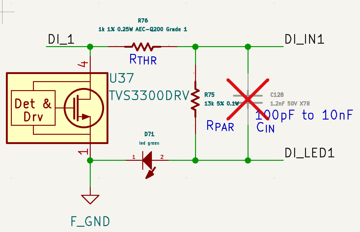
doing wrong? In my PCB I followed the design of the development board.

iso.png

  • Hi Jose,

    Thanks for reaching out.

    In order to comment on what is causing this issue for you, we need see your full schematic connection showing all the pin connections rather than just IN1 and LED1.

    Also, it will really help if you have any waveform illustrations to share on how you're seeing the wire-break enabled and nINT getting pulled low along with data on INx.

    Regards
    Varun

  • Hi Varun,

    attached my circuit.I send you waveform tomorrow.

    Thanks.

  • Hi Jose,

    Thanks for the schematics.

    There's no obvious red flag that I could see in the schematic connection.

    While probing the waveforms it is best to set both F0 and F1 as low so that there are no glitches being filtered

    Regards
    Varun

  • Hi Varun,

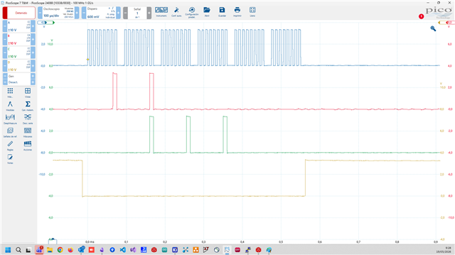
    I apologize for the delay in responding. I have attached the waveforms. 
    As you can see in the circuit diagram, I have two chips in a daisy chain configuration. 
    The waveforms you see correspond to a reading of the input states, the wirebreak register,
    and the fault register. Only the first input of the first chip is set to 1, the rest are floating.

    My lecture routine:

    void dinputsLibDinputsReadStatus() {
        uint8_t txValues[DINPUTS_CHIP_MAX_N * 3] = {0, 0, 0, 0, 0, 0};
        uint8_t rxValues[DINPUTS_CHIP_MAX_N * 3] = {0, 0, 0, 0, 0, 0};

        //read (daisy chain, set DINPUTS_CHIP_N in consonance)
        cliLibPrintDebugAsync("dig inputs read status\r\n");

        #if DINPUTS_CHIP_N == 1
        //for the first chip
        txValues[0] = DINPUTS_SPI_ADDR_WIRE_BREAK | DINPUTS_SPI_MASK_READ;
        #elif DINPUTS_CHIP_N == 2
        //for the first chip
        txValues[0] = DINPUTS_SPI_ADDR_WIRE_BREAK | DINPUTS_SPI_MASK_READ;
        //for the second chip
        txValues[1] = DINPUTS_SPI_ADDR_WIRE_BREAK | DINPUTS_SPI_MASK_READ;
        #else
        #error "please select a valid value for DINPUTS_CHIP_N"
        #endif

        //leemos registros wire break y fault (tambien se lee el estado de las entradas ya que se devuelven en el byte de direccion)
        if ( spiLibMasterExchange(dinputsDev.spiIndex, dinputsDev.spiDev, txValues, rxValues, (DINPUTS_CHIP_N * 3), (DINPUTS_CHIP_N * 3), 0) ) {
            dinputsLibDinputsReadStatusUpdate(rxValues);
        }
        else {
            dinputsLibDinputsReadStatusFail();
        }
    }


    static void dinputsLibDinputsReadStatusUpdate(uint8_t *values) {

       cliLibPrintDebugAsync("dinputs read status comm answered\r\n");

       #if DINPUTS_CHIP_N == 1
       //chip 1 (chip in1 -> pcb in1...)
       dinputsDev.inputs        = (uint16_t)values[0];
       dinputsDev.wireBreak     = (uint16_t)values[1];
       dinputsDev.fault[0]      = values[2];
       #elif DINPUTS_CHIP_N == 2
       //chip 1 (chip in1 -> pcb in1...)
       //chip 2 (chip in1 -> pcb in16..)
       //en daisy chain, llegan antes los datos del chip 2
       dinputsDev.inputs        = ((uint16_t)reverse_bits(values[0]) << 8) | (uint16_t)values[1];
       dinputsDev.wireBreak     = ((uint16_t)reverse_bits(values[2]) << 8) | (uint16_t)values[3];
       dinputsDev.fault[0]      = values[5];
       dinputsDev.fault[1]      = values[4];
       #else
       #error "please select a valid value for DINPUTS_CHIP_N"
       #endif
    }

    the function "reverse_bits" is used because the second chip has the inputs in reverse order of the numbering.


  • Hi again Varun, 

    I complete the info:

    ChA: SCLK, ChB: MOSI, ChC: MISO, ChD: CS.

    I've also noticed that the Fault pin goes to level 0 (logic active) when all inputs are 
    floating or connected to ground, and only goes to 1 (logic inactive) when all inputs are
    connected to 24V. This doesn't seem like the correct behavior, does it? Furthermore, in the first case,
    the value of the fault register is 0, which doesn't accurately reflect the pin's state.

    Regards.
  • Hi Jose,

    Allow some time to review these inputs and come back with a response by Friday, May 22.

    Regards
    Varun

  • Hi Varun,

    any progress?

    Regards.

  • Hi Jose,

    Apologies but the waveform I'm unable to retrieve any root cause form the waveform that you shared above.

    In order to debug this step by step and not diverge in all directions, let's start by the issue reported first.

    Also, it will really help if you have any waveform illustrations to share on how you're seeing the wire-break enabled and nINT getting pulled low along with data on INx.

    Please probe using an actual oscilloscope and probe setup where we see INx and nINT along with nFAULT at the same time to see the actual Input Output behavior

    Regards
    Varun

  • hI Varun,

    CHA Input IN1, CHB nINT, CHC Fault. I have tested it without pull up. Then I repeat the test with 4k7 pullup in nINT pin with same waveform.

    I have verified that if it does not read via spi, nInt remains low, which, although not explicitly stated in the datasheet, 
    seemed to be the expected behavior.


    The problem with the nInt pin was clearly due to a lack of information from the datasheet, 
    since it does not specify anywhere that the use of a pull-up resistor is necessary
    (However, The need for a pull-up resistance was my first question in this thread...)
    Regarding the wirebreak and nfault bit issue, I am still waiting for your help.

    Regards.
  • Hi Jose,

    Thanks for the inputs.

    Are you stating that having pull-up on nINT resolves your issue of wrong interrupt to MCU completely? Or are you saying that it is only after a SPI read is when nINT starts functioning as expected?

    Regards
    Varun

  • Hi Varun,

    When I use the pull-up resistor, the nInt pin stays high until there's a change in an input, and once
    that happens, it stays low until the register is read via SPI. In my understanding, this is the correct behavior.
    Therefore, your first assumption is what I meant to say.
    Without pull-up, the nInt pin always remains at 0, regardless of changes in inputs, reading of spi registers, etc.

    Thanks.
     
  • Hi Jose,

    Thanks for the clarification.

    nINT functionality with reading of SPI registers is an expected behavior but the Pull-up is something is not mentioned in the datasheet as well.

    I'll need to discuss this with design team to see if this is really a miss in datasheet - I will update you on this as well, even if you have a working solution currently.


    Here, the ChC(red) is nFAULT right? - but it looks like nINT behavior that you described. Can you confirm?

    Also, what is the timescale unit - is it 10ms/div?. Need this for discussion with design.

    Regards
    Varun