ISO1540: Wrong Acknowledge level on Side 1

Part Number: ISO1540
Other Parts Discussed in Thread: ISO1541

Hi,

I have a RPI 5 on side 1, and several I2C chips on Side 2 (e.g. MCP3428, PCA9555A, X9241).

As shown in schematics joined, I have 3.3kR on both sides.
Note: 330R resistors have been replaced by 0R. 

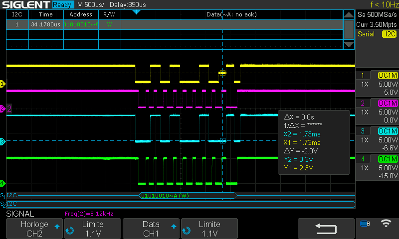
The problem is that we see well the acknowledge on side 2 (slave), but this one do not pass correctly the isolator ISO1540. The low level (acknowledge) is equal to 2.3V instead of <0.8V, with a Vcc1 of 3.3V. Then the master do not consider to have the acknowledge. See scope joined (Ch1,2: Side 1, Ch3,4: Side 2).

I have tried:

  • change pull-up with 1.5kR or higher (4.7k, 9.4k): not working; same thing
  • change the ISO1540 by an ISO1541: not working more; same thing
  • change SDA, SCL pins (3,4) by other GPIO pins (14, 15): not working; same thing
  • replace my board by a prototype board (same schematic; 3.3kR pull-up, 100nF decoupling capacitors and with one one slave, X9142): not working. same thing

What can I try more ? What's going wrong ?

Thanks

Regards,
ScreenImg-4.png

  • Hi Olivier,

    Thanks for reaching out and providing detailed inputs.

    The issue is well understood but in order to debug this further, we'll need following inputs from you:

    1. A zoomed-in scope shot (in both X&Y axis) of the ACK bit region form above shared waveform.
      1. Also let us know what is the duration of ACK bit which is being transferred from Side2 to Side1 and showing the error.
    2. In the above schematic, where is the VCC1 getting connected to C44 node connected to 3.3V?
      1. Please also share the PCB layout for us to review as the decoupling capacitors are super-critical for device performance.
    3. Can you let us know what is the VIL for the RPI used on Side1?
      1. This is in order to check the logic compatibility with Side1 of ISO1540 with VOL1(max) = 0.8V

    Questions based on your experiments:

    change SDA, SCL pins (3,4) by other GPIO pins (14, 15): not working; same thing
    1. What does these GPIO pins mean exactly? - Did you use a digital isolator? Is this issue repeatable even without ISO1540?
      1. Which device are you using for GPIO experiment?
    2. Do you have a scope shot for that as well?

    Regards
    Varun

  • Hi,

    The clock frequency is around 5kHz. Then the decoupling capacitors is no a real problem.

    In the mean time, I found the solution of this problem. The RPI5 didn't drive the outputs in open drain. 

    I've added a new configuration of output pins as open drain, and the low state goes down to 0.9V.

    Now it works.

    Thanks for your help.

    Regards