


Part Number: ISOW7742
I have tested my equipment based on ISOW7742FDFMR by IEC 60601-1-2 (class A emissions). The test results showed a very narrow margin from the limits in the 50 to 60 MHz range (graph below, limits for 3m distance from the antenna, horizontal polarization - vertical is not relevant for this discussion).
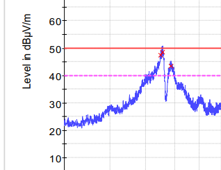
My equipment is connected to another via an isolated RS-232 port, with the ISOW7742 and a MAX3232ECPW level converter.
We requested the test lab to add snap-on ferrites (nominal impedance of 170 Ohms at 100 MHz, 75 at 25 MHz) close to the DB-9 connectors. That resulted in:
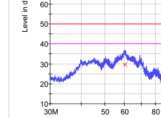
The quasi-peak mark is 20 dBuV/m below the limit.
I am trying to troubleshoot the board to determine the root cause and, if possible, to fix it without adding ferrites to the cable. I am using an RF amplifier with near field probes (mostly magnetic) connected to an oscilloscope with FFT function.
For reference, this is the board at the region of interest:

I found with the near field probes that there are spread-spectrum components when the probe is placed near the ISOW7742 (obviously) but also in the DB-9 connector vicinity. I believe this magnetic field induces common mode conducted currents that travel along the serial cable that becomes an antenna. Adding the ferrites suppresses these currents.
I tried my best to follow the guidelines of the SLLA561 document, despite the limitations imposed by the geometry and PCB real state of my board.
Below are the relevant parts of the schematic.
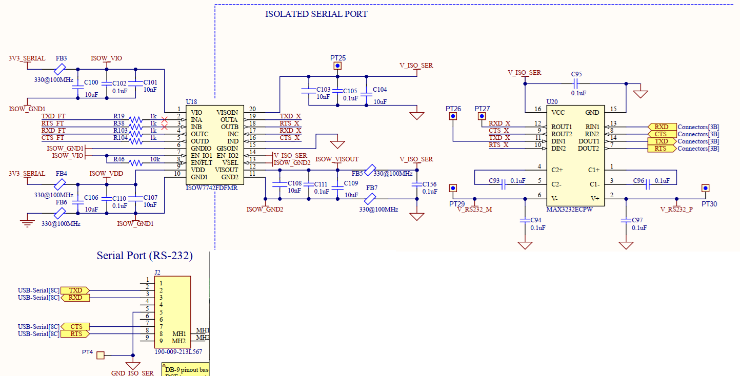
Below, the top and bottom layers and down below, I added one of the inner layers (all the four inner layers follow similar geometries). I may send the gerber files and schematics by email, if necessary.
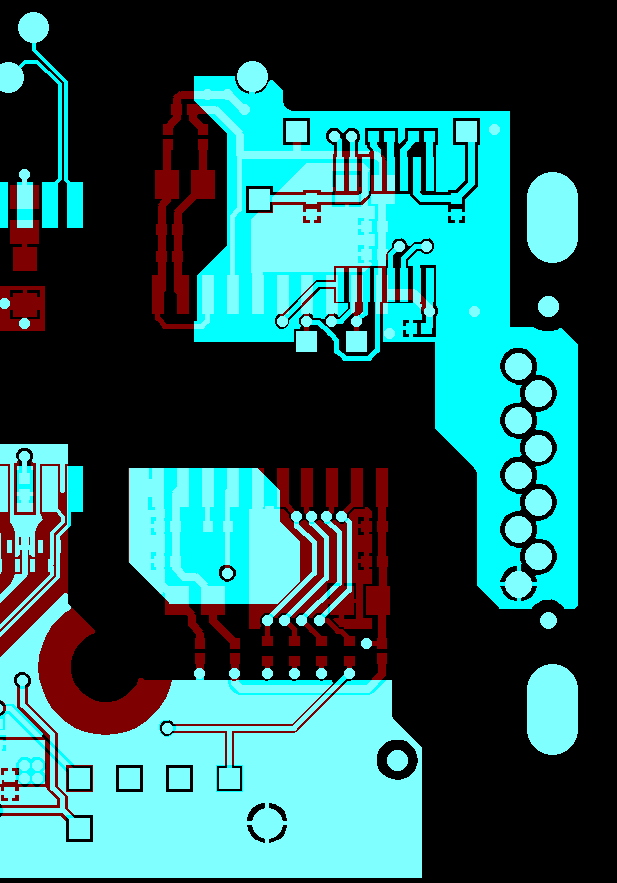
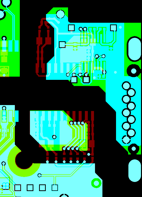
Is there a way to solve this issue at the PCB?
Note that to check if whatever fix (other than the ferrites) I apply to the design, I will have to schedule a few hours in the test lab. It is OK, but I need to have a defined protocol with potential fixes to verify their effectiveness.
Thank you in advance for your support.
