This thread has been locked.

If you have a related question, please click the "Ask a related question" button in the top right corner. The newly created question will be automatically linked to this question.

ISO35TDWR isolation issue

Other Parts Discussed in Thread: ISO35, ISO35T

Hi,

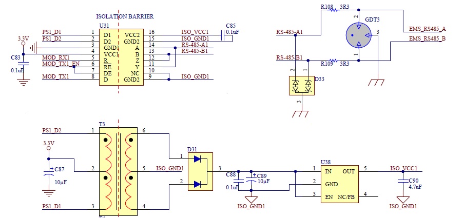
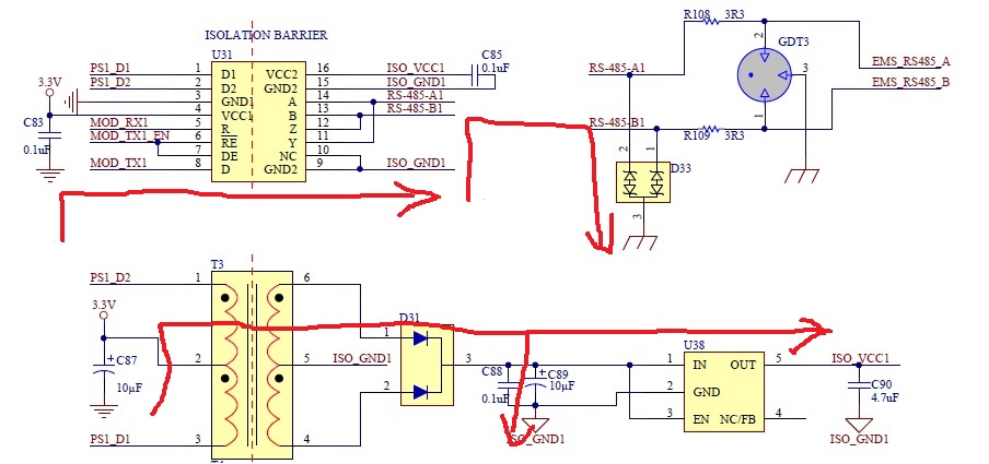
I am using ISO35 for RS485 communication in my design but after the hi-pot test at 1700V, this transceiver does not work anymore. I have found out the transceiver and rectifier on secondary side of HF transformer were both damaged.

As stated by TI, this transceiver is rated for 2500Vrms of isolation.

Is there anyone has ever experienced this before?

Any response/advice would be highly appreciated.

Thanks

  • Hi LL
    I've moved your post to the Industrial Interface Forum so the appropriate experts can answer your question.
    Best regards,
    Jim B
  • LL,

    What is the nature of the 1700V that you used is it AC or DC. Note that the DC working voltage of VIORM is 560Vpk. The 2500Vrms UL rating is for 60Hz sine wave. Also note that transformer that you chose would also have a similar specification on the DC voltage.

    Regards,

    Sarangan

  • Thanks Sarangan,

    The hi-pot test is DC voltage at 1700 Vdc only for 1 second and the transient voltage VIOTM of 4242Vpk should be applied in this case as VIOTM is 60 seconds rating.

    The VIORM of 560Vpk is the DC working voltage and the transformer isolation voltage used was rated for 4000V.

    After DC hi-pot test, the transformer was safe but the damage randomly happened with ISO35T and at the same time the HF rectifier on the isolated side.

    Please correct me if I was wrong but the quality of this transceiver is the one I am thinking of now.

  • LL,
    If the test is for just 1s I don't expect the ISO35T to fail. On the failing units what is the fail signature. Can you see if the Isoaltion impedance is still intact. Also it possible to check without the transformer once and without the ISO35T once. also is there a Y capacitor between GND1 and GND2.
    It will be helpful if you can share the section of schematic.
    Regards,
    Sarangan
  • Hi Sarangan,

    I use recommended schematic from the spec http://www.ti.com/lit/ds/symlink/iso35t.pdf and there is no cap between GND1 and GND2.

    The transformer isolation is rated for 4kV and this is safe for all the tests.

    The DC hi-pot test normally was carried out  at 1700Vdc for 1 second but I have tried at lower level of 800Vdc for 1 second and the ISO35 gets damaged already which either no voltage on Vcc2 -3.3V or with voltage but no communication as the impedance of A and B reduces significantly.

    Then the unit gets fixed and AC hi-pot test was carried out at 1000Vrms/60Hz and it passes but again the spark happened on ISO35 when voltage increases up to 1200Vrms/60Hz. This ISO35 is rated for 2500Vrms!!!

    The DC/AC hi-pot voltage was applied between GND1 and PE - not directly connected with GND2, please refer to schematic below

    When I have mentioned about failure, most of the time the current is low, it passes the hi-pot test but it results into ISO35 damage. A few times it fails both current and ISO35 damage.

    Thanks,

  • Lily, Where do you see the spark happening. A spark happening it self is an indication that high energy is finding some other path other than through the Isolator. Is it possible to share the layout of this section of the board?

    Also what is the rise fall time of the DC voltage that is applies. If it is too fast this could monetarily take the Iso_Vcc1 very high destroying the devices.

    Have you seen ISO35T fail without the rectifier failing, transformer rating of 4kVrms is again only a AC rating . Please check the DC rating or share the part number for us to check. Shown below are potential current paths when the high voltage is applied. To rule out some of these, please test the same with out the transformer and Vcc2 of Iso35T powered from a battery.

    Regards,

    Sarangan

  • I used the same PCB board which has failed earlier and re-populated all parts and carefully cleaned the board by myself. Transceiver, transformer, TVS, rectifier...were populated one at a time and the 1200 Vacrms hi-pot test was applied in between every component population - 1200Vacrms and 1700Vdc are both acceptable for our hi-pot test . It has passed every single change and no damage happened.

    I was now thinking about the cleaning quality during the part assembly process which might result in the leaking path under components: transceiver/transformer or we might need to discharge  remained energy from the boards before doing hi-pot test.

    Just looked at the transformer and it is rated for 4000Vdc.

    Really appreciate your response Sarangan.

    Thanks,