This thread has been locked.

If you have a related question, please click the "Ask a related question" button in the top right corner. The newly created question will be automatically linked to this question.

SMBUS compatibility of iso1541

Other Parts Discussed in Thread: BQ78350, ISO1540, ISO1541

Hello,

We are using the ISO1541DR as an isolator between a logic system using an STM32-based ARM chip and a battery containing a TI bq78350 chip. We find that the communication does not work with the isolator, however if we bypass it then it works. 

The SMBUS on the battery side has 200ohm series resistors and 5.6V zener protection diodes on the clock and data lines. On the ARM side we have 2.4kOhm pullups on either side of the isolator and followed the guidelines for recommended layout. Because we are using the version of the device only for one master, side 1 is connected to the ARM chip and side 2 to the bq78350 chip. We are running the bus at 100kHz.

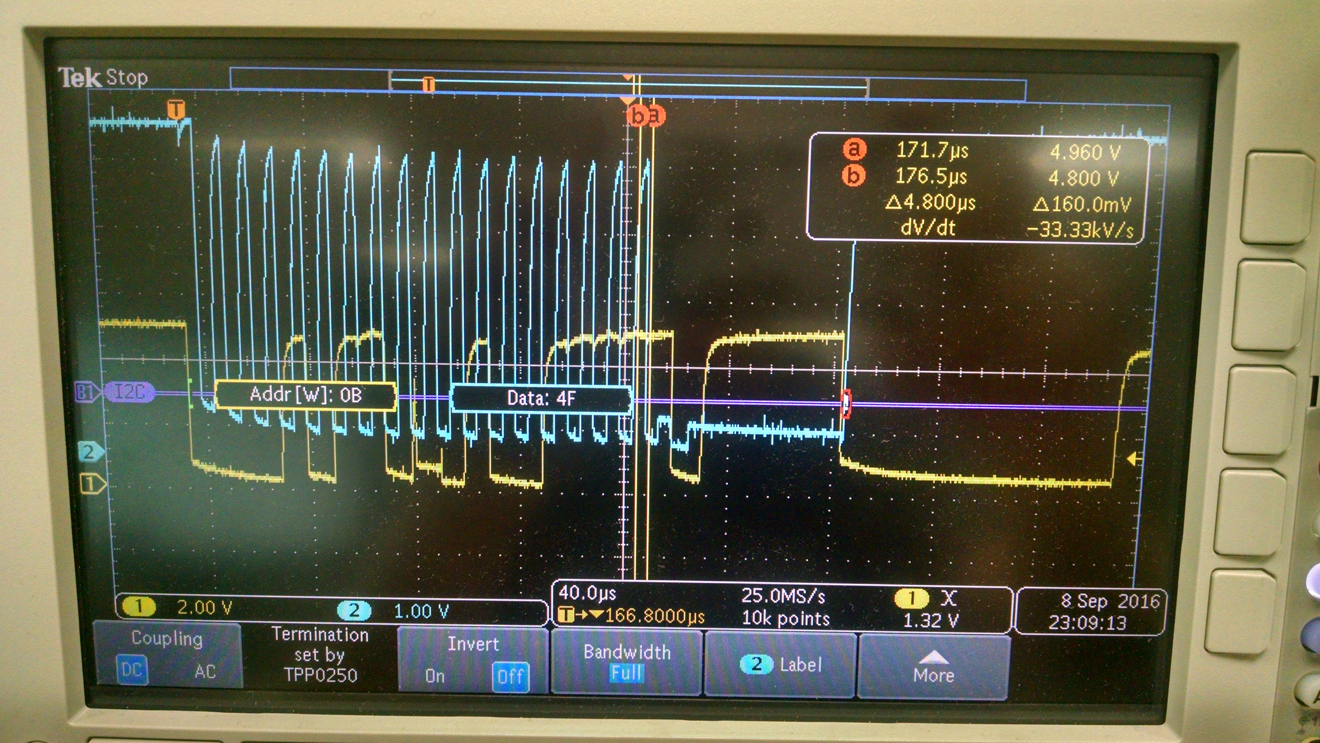
Shown below is a screenshot of a scope hooked up to the clock (blue) and data (yellow) lines close to side 2 of the isolator. The length of connection between the isolator and battery is about 18inches 22AWG, which may explain some of the variation in logic low levels due to ground offsets. However, I am concerned about the logic low levels initiated by bq78350 and whether the isolator is translating them to side 1.

Regards,

Forrest

  • Hi Forrest,

    The logic levels measured still seem to be be within the recommended limits of ISO1540. I am afraid more investigation is required to debug the problem.

    Could you please:

    1. Plot the side1 signals along with side 2 to see what's happening and if there is any data missed, and which transitions are affected.

    2. Reduce the length of the AWG connection to see if things will improve.

    3. Reduce the value of pull up resistance on side2 to 150 Ohm to see if things improve. The waveforms are not settling with the current pull up resistance value. 

    4. Measure voltage drop across the AWG in the signal lines. 

    5. Check ground potential difference between the bq and the isolator.

    Rgds,

    Anant

  • Thanks Anant,

    We believe we have found the source of the problem. We swapped the ISO1541 with the ISO1540, which has the bidirectional clock line. This should be unnecessary since we have a single master on this bus but it was working after this. It looks as though the bq78350 chip is frequently clock-stretching the clock line and because our ISO1541 has a unidirectional clock the ARM chip wasn't seeing the stretching. Any thoughts on this?

    We also tried lowering the pullup values to 1kOhm which improved the waveform but wasn't the determining factor. Other issues such as ground potential difference and voltage drop through the board have been in the low 10's of millivolts.

    Regards,

    Forrest

  • Hi Forrest,

    I think your observation explains the issue. I2C allows the slave to stretch the clock if it is not ready for more data, and the only way the master can know of this is if the clock is bi-directional.

    Rgds,

    Anant

  • I'm surprised the datasheet for the ISO1541 doesn't point this out. It states in the first page that a unidirectional clock line works for single-master based I2C bus systems.
  • Hi Forrest,

    The datasheet is indeed misleading - the sentence you refer to does not comprehend clock stretching by the slave. I apologize sincerely for the inconvenience. We'll address this in the next revision of the datasheet.

    Rgds,

    Anant