This thread has been locked.

If you have a related question, please click the "Ask a related question" button in the top right corner. The newly created question will be automatically linked to this question.

ISO7820LL: LVDS communication question

Part Number: ISO7820LL

Hi,

I use ISO7820LL to transmit LVDS signal. But i met a question on GND.

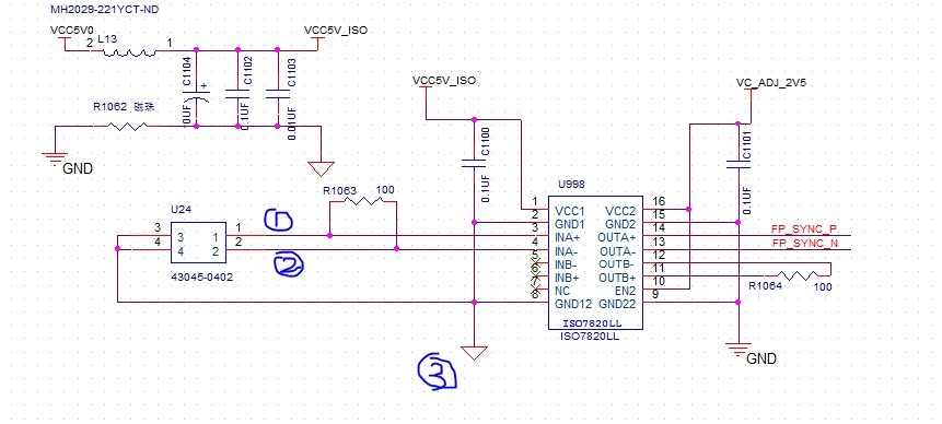
Please refer below schematic,

If 3(the VCC1 GND of ISO7820LL) is connection for VCC1, OUTA+ and OUTA-(FP_SYNC_P, FP_SYNC_N) is no output.

If 3(the VCC1 GND of ISO7820LL) is connection for the reference ground of 1 and 2 (INPUT LVDS signal), the output of  OUTA+ and OUTA-(FP_SYNC_P, FP_SYNC_N) is OK.

The GND1 should be connection for VCC1 shown in datasheet, but why fail in the actual test.
Thanks,

Walsh

  • Hi Walsh,

    I am not sure if I completely understand your question, if possible please do elaborate a little more about your observation especially the GND connections.

    The reference GND of input LVDS signal should be connected to GND1 of ISO7820LL for the device to be able to interpret the input signal. If the reference GND of input signal is not connected to GND1 of device then the device will not read correct signal voltage levels as per the datasheet.

    Please let me know if this answers your question, thanks.


    Regards,
    Koteshwar Rao
  • Hi Koteshwar:

    Thanks for your explanation and it's corresponding with our test result.

    Thanks,
    Walsh