This thread has been locked.

If you have a related question, please click the "Ask a related question" button in the top right corner. The newly created question will be automatically linked to this question.

ISO1212: ISO1212

Part Number: ISO1212

Hi 

We are using ISO1212 for Isolation purpose for 24V , 48V DC Digital Section and for AC Section of 230V AC.As per the Threshold Calculator  and application note

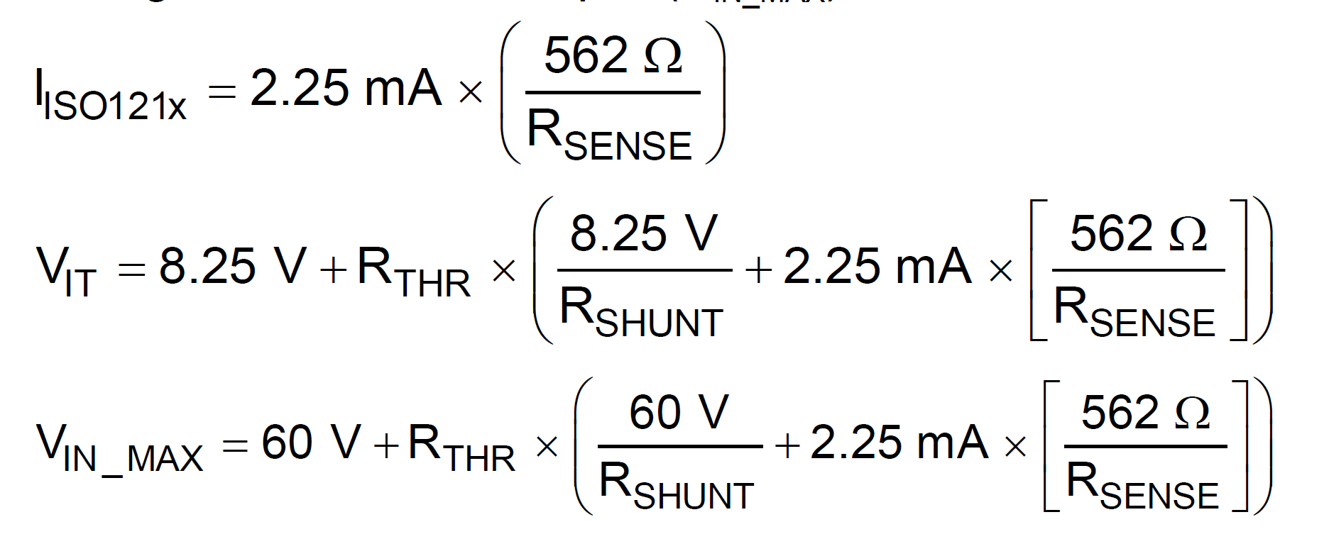
" How to Design Isolated Comparators for ±48V, 110V and 240V DC and AC
Detection TI TechNote." 

We want to know how the voltage to IC pin will be less than or maintained less than 60V - as per datasheet Rshunt will take care maintaining voltage across the pin.

Can you give us explanation/ calculation details on this section how different values of Rth and Rshunt will maintain 60V 

  • Hemalatha,

    Rth and Rshunt form an initial voltage divider than will bring the high voltage down to a lower value depending on the values. This is why the value of Rth increases as the system voltage increases.

    Respectfully,
    Lucas
  • Hi Lucas

    thanks for the reply

    Rth and Rshunt forming as voltage divider plays vital role in case of voltage higher than 48V or more

    Eg : Rth = 60.4K and Rshunt = 15K for AC input of 230V what will be voltage at IC pin ?
    could you elaborate and explain along with calculations , it will be helpful
  • Hemalatha,

    In the document you referred to in you earlier post there is a set of equations to calculate the needed resistor values. Other than the voltage divider, 

    the current through the ISO121x (2.25mA for RSENSE=560) will lead to additional drop across RTHR. The maximum voltage on the SENSE pins of the ISO121x device is 60 V. However, because the RTHR resistor drops additional voltage, the maximum voltage supported at the module inputs is higher. The values are calculated in such a way that voltage at the IC pin will not exceed 60V. 

    Respectfully,

    Lucas 

  • Hi Lucas

    How the voltage will drop when Input = 230V AC

    will voltage drop at Rth and then forms voltage divider with Rshunt

    (or)

    forms Voltage divider with Rshunt and then drops the voltage ?

    Could you take an example and elaborate calculations how the voltage drop is seen from input voltage to IC pin.  

  • Hi Hemalatha,

    Lucas is currently on travel, I will try to help you in his absence.

    I believe the points that Lucas has brought out already answer your question, I will try to rephrase them to see if it clarifies your question.

    The field input (DC/AC) is applied to RTHR pin directly while the other end of RTHR is connected to SENSE pin of ISO121x. RSENSE sits between SENSE and IN pins and there is some internal circuit inside device between IN and FGND pins. So if you look at the circuit, RTHR, RSENSE and the internal circuit form a voltage divider with three components in series. The voltage appearing across RSENSE and internal circuit is what is seen by the SENSE pin while IN pin see slightly lower voltage than SENSE pin.

    Now we can always choose the value of RTHR such that most of the voltage drops across RTHR while a small portion appears at SENSE pin. The equations listed in datasheet and application note are implemented in the threshold calculator. As stated in the threshold calculator, when RTHR = 60k, RSENSE = 560 and RSHUNT = 15k, the device accepts 240Vrms AC and HIGH threshold is set at 125Vrms AC.

    From ISO121x datasheet, VIH and VIL thresholds at SENSE pin are 8.2V typical and 7V typical, respectively. This means that, when field input is 125Vrms AC the sense pin sees only about 8.2V due the RTHR & RSENSE resistor divider for the above mentioned RTHR, RSENSE and RSHUNT values.

    Please note that RSHUNT is added only to keep RTHR not get very high, without RSHUNT the value RTHR can go very high. I hope this post clarifies the question you had. Let me know if there is anything that is not clear to you, thanks.


    Regards,
    Koteshwar Rao