This thread has been locked.

If you have a related question, please click the "Ask a related question" button in the top right corner. The newly created question will be automatically linked to this question.

ISO1050: Communication Delay Issue

Part Number: ISO1050
Other Parts Discussed in Thread: ISO1042

Hi,

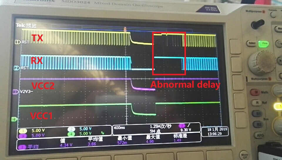
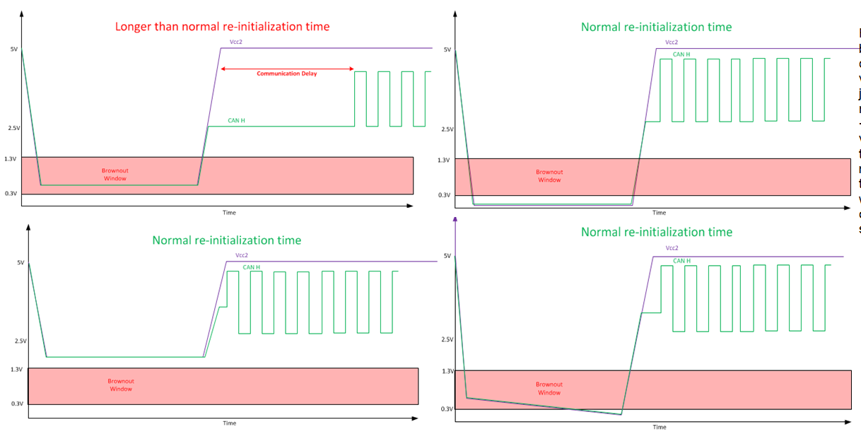
My customer got below issue, when they switch on/off the 12V power supply, sometimes the CAN communication is 300ms delayed, details are in the captured waveform as below, could you please help? Thanks. 

  • Sorry I need to correct two typoes. The CANH on the waveform is differential CANHL close to 1050, CANL is the differential CANHL on the bus.

  • Hi Wayne,

    Thank you for asking your question on E2E and attaching these scope shots with annotations. They are very helpful for illustrating the issue you are seeing.

    It looks like Vcc2 is not discharging entirely to 0V. Could you perform an additional experiment for me? Can you add a bleed resistor to Vcc2 to ensure it discharges down closer to 0V and see if the issue still persists?

    It will also probably be helpful if I can get a look at the schematic around the ISO1050 part. Would you be able to provide this? I understand if your customer is wary of posting a schematic on a public forum. If this is an issue please let me know and I can set up a private message for us to share confidential information.

    Best regards,
    Dan
  • Wayne and I are communicating over private messages to discuss confidential customer information. I will close this thread for now and will post a summary of the resolution when it is found.

    Dan

  • Hi Wayne,

    Your customer is experiencing this communication delay issue because Vcc2 is not discharging down to 0V before the supply is brought back up.

    The ISO1050 needs to have the supply brought below 0.3V (and ideally as close to 0V as possible) to ensure that a communication delay is not present. The following graphic illustrates which conditions lead to the communication delay and which do not.

    The brownout window, 0.3V to 1.3V, represents the range of voltages in which a longer than normal re-initialization time may occur if Vcc2 powers up from this voltage.

    This communication delay varies in length over voltage and temperature. Worst case delays can be in the order of seconds for -55°C for 0.45V.

    The ISO1042, an upgraded device with higher isolation rating, CAN FD speeds of 5 Mbps, higher bus fault-protection voltage, better EMC performance, and smaller package options does not exhibit this behavior. For all new designs, it is recommended to upgrade to the ISO1042.

    If the ISO1050 must be used, it is important to ensure that the power supply will discharge to 0V so that a longer than normal re-initialization time does not exist. If the power supplies cannot be configured in such a way that they discharge below 0.3V on their own, one can implement a bleed resistor between Vcc and GND. The bleed resistor value should be selected such that it ensures Vcc goes below the brownout window fast enough for any power interruption or power down sequence the system may permit. The lower the resistance, the faster Vcc will discharge to 0V at the cost of burning power. For many systems, a bleed resistor value of 2KΩ will work.

    Let me know if you have any questions.

    Best regards,

    Dan