Other Parts Discussed in Thread: ISOW7842
In mass production my customer has met with failures of ISOW7842 . The ISOW goes to short current by second ( ISO ) side.
Could you revise the scheme and suggest the ways to resolve the issue?
There are technical details in attachment:
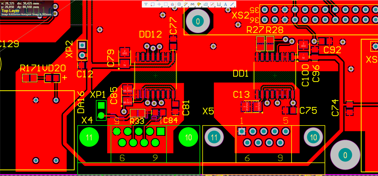
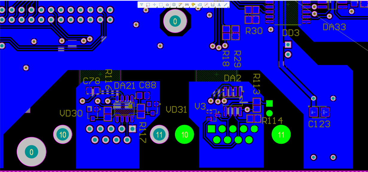
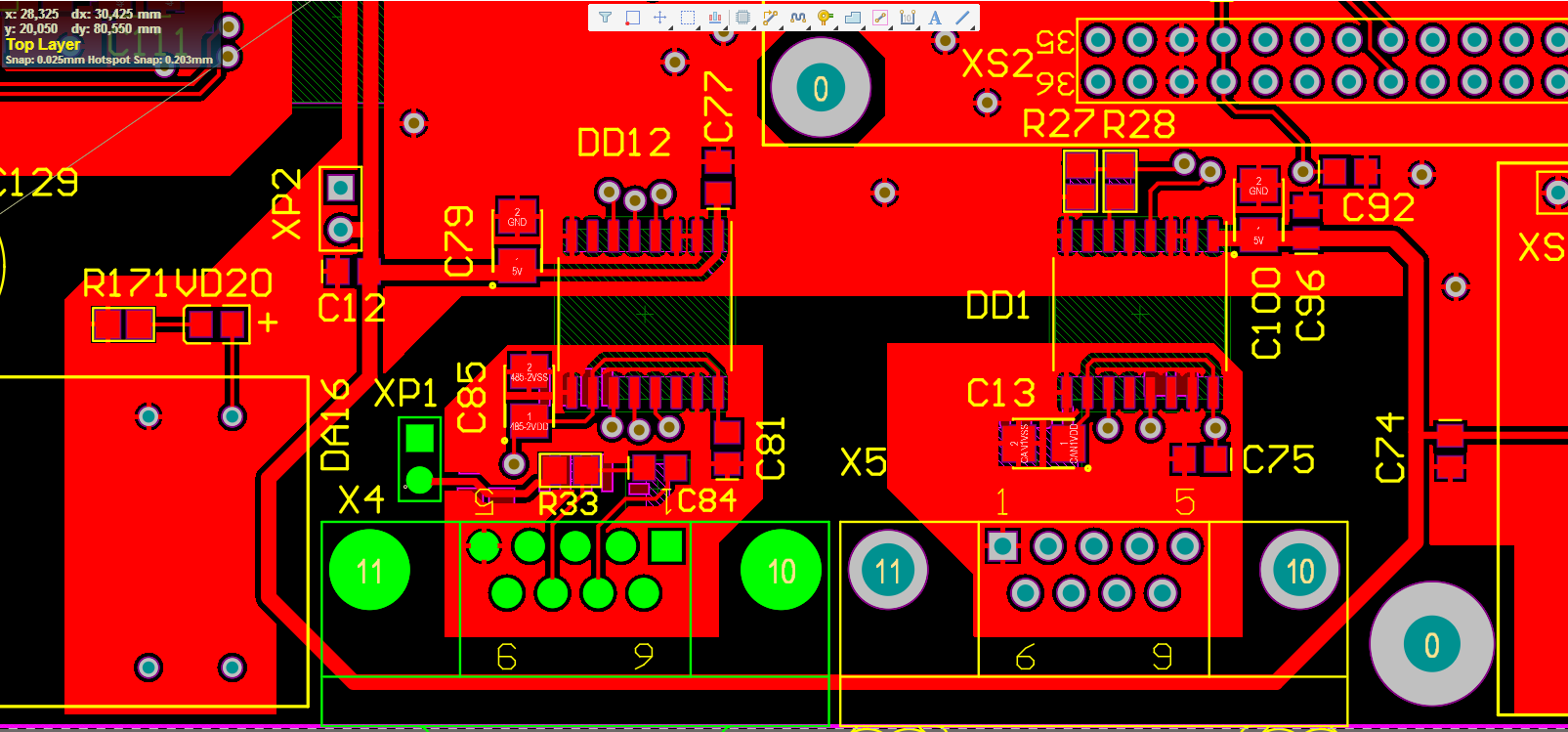
- TOP.png and BOT.png – are PCBs
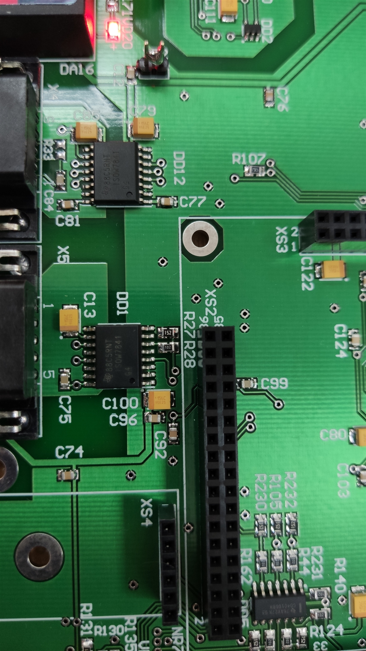
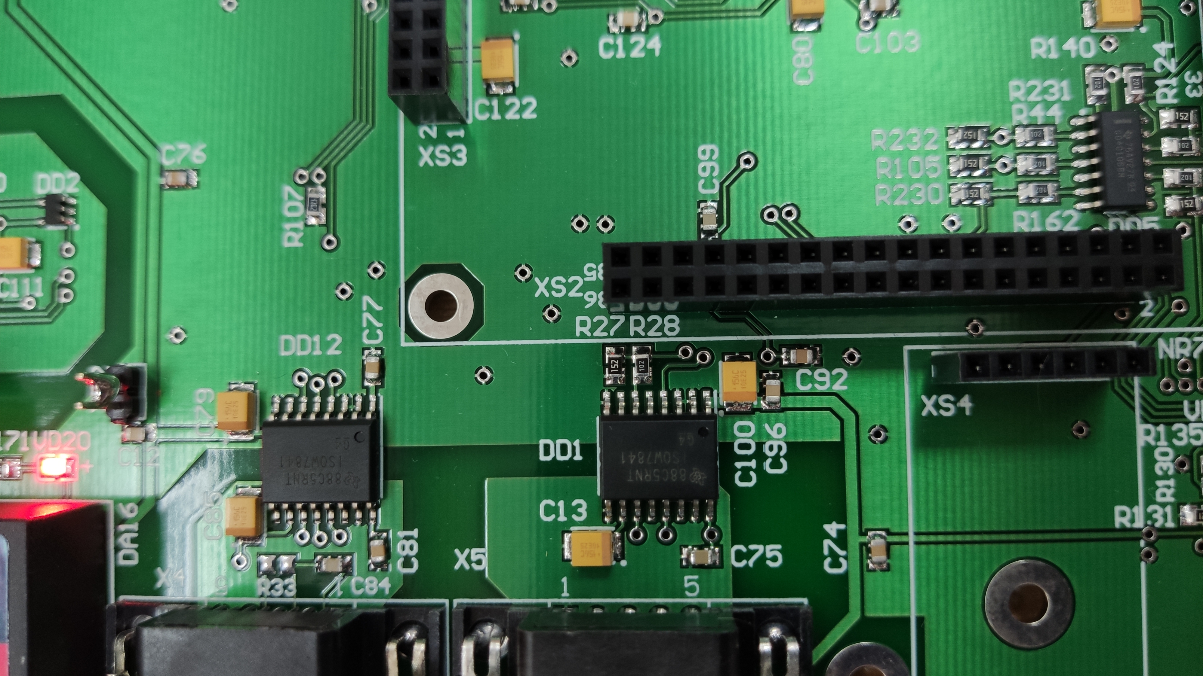
- IMG 20190903……jpg – board’s photo
- BldcPmsm.pdf - schematic
- BldcPmsm.pdf