This thread has been locked.
If you have a related question, please click the "Ask a related question" button in the top right corner. The newly created question will be automatically linked to this question.
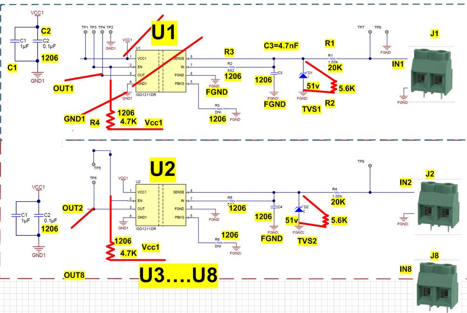
Is this evaluation Board IC capable to detect high voltage impulse 200V with short durations 
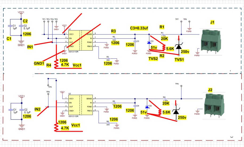
1ms and convert it to 5V
Abraham,
By "this evaluation Board IC" do you mean the ISO1211 EVM with changed and added components from the schematic you posted? Id so, then a 200V input from J2 will be reduced to 43.75V due to the 20k and 5.6 resistors. The VIH threshold will typically be 82.65V based on this configuration and will read as a logical high if there is a 200V input. This calculator document helps determine what the logic thresholds will be based on the resistor values.
Respectfully,
Lucas
TVS1,TVS2.pdfTVS1,TVS2.pdfHello Lucas
yes, I am doing modification for the evaluation board to accept 100V ...300V at the input.
Can this design take high pulse input and converted to 5v pulse ???
is my design/Modification okay ???
how about TVS 250V and 51V ??? are they okay???
Abraham,
What is the system's intended input range and what are the intended logic thresholds? I need this information in order to verify that the resistor values you have chosen are correct. I would also need to know the data speed in order to determine if the value for C3 is correct. What is the application you are designing for?
Yes the ISO121x can take in "high" input signal voltages and output 5V digital logic. One uses the equations in the datasheet or the calculator document to determine what values of resistors to use for their particular system.
The 250V TVS diode is fine as long as you are expecting less than 250V input signals. Also the TVS diode needs to be rated for the proper amount of surge current that you may be trying to protect against. The 51V TVS diode looks ok.
Respectfully,
Lucas
Abraham,
Thank you very much for including the scope shot of the pulse. The ISO121x needs minimum pulse width of 150ns. Is this pulse longer than 150ns? The time division is 25ms for oscilloscope so I can't tell by looking at the image.
Respectfully,
Lucas
Abraham,
Ok. Voltages above 250V will be clamped by the TVS diode. Will the input be typically less than 250V? Is the 300V max as described before only for margin?
Respectfully,
Lucas
Hello Lucas
Voltage max from engine trigger 300V
as attached TVS spec breakdown 279 to 309
Hello Lucas
Another Question...
can I use buffer in front of output ..????74HC7541D(schmitt trigger,buffer)U9.pdf.
Abraham,
Thanks for providing more information. Since your expected typical input is up to 300V, then those TVS diodes need to be removed. The 250V TVS diode clamps at 400V which wouldn't be very helpful. The 51V diode can trigger at the 300V input and shouldn't be used. Is there a particular surge rating that you are trying to achieve?
C3 and C4 should be reduced to about 4.7nF so it doesn't filter out your 1ms pulse.
You can use an external buffer for the ISO1211 output but these features are already built into the ISO121x devices. There is already an internal schmitt-trigger and output enable.
Respectfully,
Lucas
Hello Lucas
We need some kind of protection coming from trigger input and at the input of IS01211
The idea is to prevent any signal above 300V at the input
also to prevent IS01211 to see pulse above 60V which is the max limit for the chip
What is recommendation for protection ??
TVS type????
Hello Lucas
we need some kind of protection at trigger input and input of chip
any suggestions for best strategy for protection ???
You can increase Rthr to 27k to increase the maximum voltage at module input to just over 400V. This would be just over the clamping voltage of the diode you mentioned before. Note that the diode will start to break down still at 250V. The input threshold voltage will be just over 100V which should work for your expected pulse.
You maybe be able to find a TVS diode that has a clamping voltage between 300V and 400V but has a breakdown voltage of higher than 250V.
Abraham,
I would recommend keeping the other 250V TVS diode instead and increasing Rthr to 27k as depicted in my previous post.
Abraham,
Do you intend to change Rthr (R1 and R4) to 27k? Doing this is the only thing to make the 250V TVS diode make sense.
Abraham,
I see you have also changed the 250V TVS to a 350V one. Does this new TVS diode have a clamping voltage of 400V or under?
Abraham,
The clamping voltage of the TVS in question should be under 400V. This new one has a clamping voltage of 567 and I do not recommend this. Would you like to have a conversation about this? This thread is getting busy with all the diode/resistor changes. You can PM me if you like to discuss a phone conversation.
Hello Lucas TVS data sheets is attached.. which one do you prefer for input ??
I will provide that via PM. Please accept my friend request so that we can discuss the phone call via PM and not on the public thread.
Hello Lucas
On Friday, I was testing your evacuation board with modification 27K and 5,6K. I applied 150V pulse and monitor 5V output
the delay measured 3us..... it seems too high ???
any reason ??
Abraham,
You can try removing or reducing C3/C4. This is most likely the highest contributor to the delay.
Respectfully,
Lucas
Hello Lucas
I am using TI evaluation Board with modification by adding 27K and 5.6K.
NO capacitors C3/C4 on board.. I will send you scope and probe set up
It appears you are measuring the input before Rthr. Are you able to measure past Rthr?
Also, the TVS diode may have significant capacitance that is forming an RC filter with Rthr which is a relatively large value of 27k. Could you try the measurement again but with the TVS diode removed?
Hello Lucas..
My team asked me question about HV signal input. what happened if the signal pull down.. is your chip will trigger on rising edge only ???
Abraham,
The ISO1212 triggers based on the thresholds determined by the resistors. If the input signal is pulled down below the VIL threshold, then it will output low.