Other Parts Discussed in Thread: ISO7841
We plan to use the ISO7821 DWW16 within a gate drive system for IGBT traction converters in railway application. The shape of the working voltage over the component is rectangular in a chopper function with resistive load (over voltage limiter). The rms voltage value is in this case depending on the modulation degree between the pulsewidth and on time, which can be between 0% up to 100% according Urms = UIOWM = U_dclink * square root (t1/t).
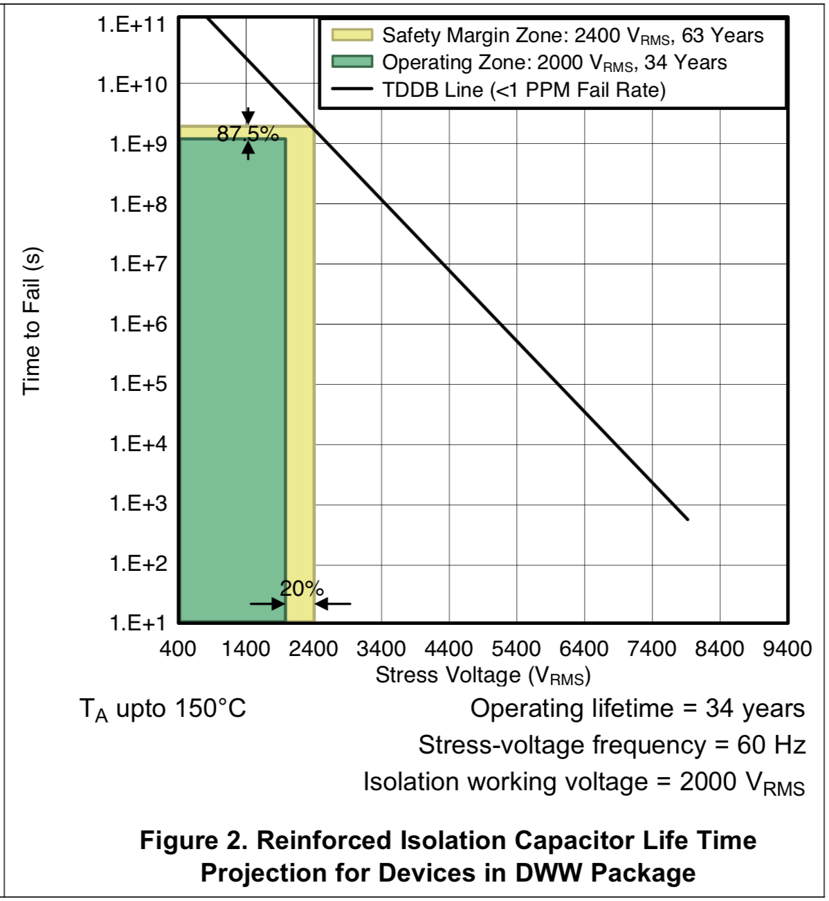
The application maximum voltages are
Maximum repetitive peak isolation voltage VIORM (PK): 2770Vpk (ISO7821 data sheet max value = 2828Vpk)
Maximum working isolation voltage VIOWM (DC): 2300Vdc (ISO7821 data sheet max value = 2828Vdc)
Maximum working isolation voltage VIOWM (RMS): 2185Vrms (ISO7821 data sheet max value = 2000Vrms)
The application maximum values are below the datasheet values except the VIOWM (RMS). This value is exceeded by 185Vrms. This operation point of the converter is approx 1% of the total life time.
For my understanding, we are below the isolation and lifetime relevant values, the VIOWM (RMS) is some kind of "calculated equivalent" for the DC values .Maybe the time dependent brake down (TDDB) test has been carried out with a sinus shaped test voltage only.
Question 1: Can we use the ISO7821 in our application even we exceed the VIOWM (RMS)?
Question 2: Is it possible to conduct the TDDB test with a PWM shaped voltage to verify the lifetime? If yes what is the test specification?
Question 3: Is there an alternative component or maybe stacking of 2 in series (with defined centerpoint). Stacking is not a preferred solution.
This component is very intresting for traction converter in railway systems, as we have sinus- and rectangular shaped voltages, depending on the converter function.
Thank you for you valuable answer, and please come back with detailed questions
Klaus