Because of the holidays, TI E2E™ design support forum responses will be delayed from Dec. 25 through Jan. 2. Thank you for your patience.

This thread has been locked.

If you have a related question, please click the "Ask a related question" button in the top right corner. The newly created question will be automatically linked to this question.

ISOW7841: Using more than one isolator causes strange noise in the SPI MISO/SOMI signal

Part Number: ISOW7841
Other Parts Discussed in Thread: ADS1220, ISO7741

Hello all,

I am currently designing a controller for one of our lab-furnaces. I use a two ISOW7841 (with the F-suffix) as digital isolator for two ADS1220, to prevent noise in the measurement. This works great as long as I just use 1 ISOW7841. However, as soon as I solder the second ISOW7841 , I get some strange noise in the signal (onboard chip temperature of the ADS1220):

 If I remove all except one ISOW7841, everything works as excepted, no noise. But if I add both, I always get this noise spikes. Sometimes its better, sometimes its worse. Usually, one ISOW-ADC combo gives a better result: 

The strange thing is that as soon is a start heating the “idle” isolator with a soldering iron, the noise completely disappears, but comes back as soon as it gets cold again.


I already tried completely new parts (new ADS1220, new ISOW7841, and also started with a fresh PCB and new parts), but the noise is always present. So it seems that there is some problem with my PCB design, but I don’t know what it could be. Here is the schematic of how I connected the ISOW-ADC, it's mostly the same for both ADS1220 (the difference starts behind the AIN0-AIN3, but are yet not soldered onto the pcb):


I am very thankful for every kind of feedback/input


Best regards
Manuel

  • Hi Manuel,

    Thanks for sharing all the details related to the issue you are facing.

    I took a look at the schematic and I do not see any major concerns. I have also review the PCB layout and I didn't see any major concerns on that either.

    If I had to point out one thing in the PCB layout, that would be on the way the SPI lines are being connected to the connector A1. I see that all the SPI lines from ISOW7841 devices going to the controller are kind of connected in a daisy chain fashion where the traces from one device go to another and the traces from the last one go to the connector. A better way to connect these traces to the connector A1, is to have one set of traces running vertically and then branches running from this bus to individual ISOW7841 devices. This way all ISOW devices are connecting to the connector directly though the bus.
    This might or might not be the cause of the problem that you are facing but this is one of the general best practice guidelines.

    Regarding the waveform that you have shared, I couldn't really interpret the voltage and time scales of the waveform. Could you please share one screenshot of oscilloscope where both MISO at ISOW7841 input and MISO at ISOW7841 output are captured so that we will be able to compared them better?
    Please do also mention if MISO line is being held at one state (HIGH or LOW) or if data is being transmitted at a particular datarate.

    Look forward to see the data requested, thanks.


    Regards,
    Koteshwar Rao

  • Hi Manuel,

    Please do help me with the above requested data help debug the issue, thanks.


    Regards,
    Koteshwar Rao

  • Hi Koteshwar,

     thanks for your help, sorry for the delayed reply.

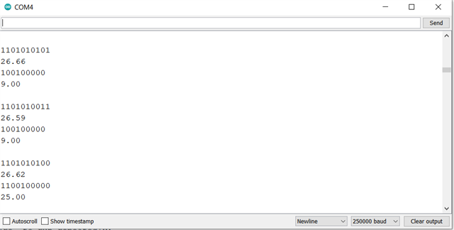
    The waveform you see in the screenshots are just readings from the serial port (chip temperature in °C of the ads1220). I tried both variants: just communicating with one device (continuous high for the other CS pin), and alternating communication per loop. It didn't make any difference. I can't really quantify the datarate, but I get about 50 readings per second. I tried to adapt the timing of the communication but that also didn't help. It seems that the MISO line sometimes interprets 1s as 0s. The screenshot shows:

    - First row: binary representation of chip temperature of the ads1220 at the bottom (PCB layout)

    - Second row: chip-temperature of the ads1220 as decimal in °C at the bottom (PCB layout)

    - Third row: binary representation of chip temperature of the ads1220 at the top (PCB layout)

    - Fourth row: chip-temperature of the ads1220 as decimal in °C at the top (PCB layout)

    The 9 °C of the top-ads1220 are failed readings (as is the 25°C). But i get similar missed readings for the bottom ads1220, but much less frequently. From this POV, it seems that the routing may be the cause of the issue?

    I do yet not have access to an oscilloscope, but will get one tomorrow or the day after tomorrow. I will then come back with the readings. Hopefully, we can fix the issue.

  • Hi Manuel,

    Thanks for sharing additional details, now I am clear about the data that you have shared. Yes, it would be hard to debug by only looking at the data received in bits. I will look forward scope shots of both input and output in the same scope shot, thanks.


    Regards,
    Koteshwar Rao

  • Hi Koteshwar,

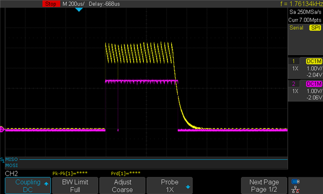
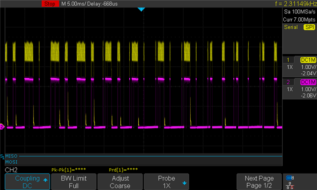
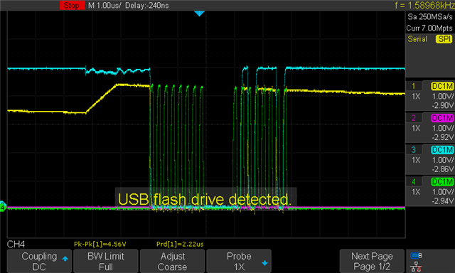
    I have to say that i just began to work with an oscilloscope, but it seems really helpful.. I hope this screenshot helps: The yellow curve is the isolated MISO line, the purple one the Arduino-line. While the yellow one peaks at around 3.3V, it just gives back ~2V. At the moment I just use an Arduino nano for communication. Do you think that this is the root of the problem?  

    one more edit:

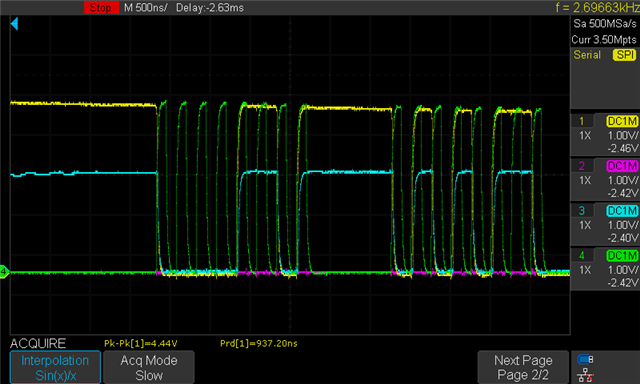
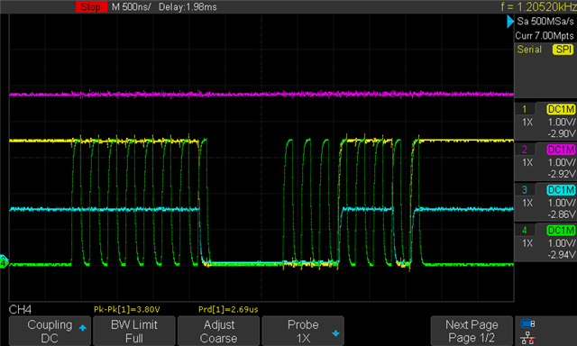
    The first two screenshots are just "floating" behavior. I now captured alos the CLK_iso and CS_iso. It seems that the MISO_iso line is floating  sometimes (on the left of the screenshot), when i do not communicate with the ADS1220. So that may be the problem? Any thoughts here? edit again: it starts floating when CS goes low, so seems to be correct behavior. 

    Yellow: MISO isolation

    Purple: CS isolation

    Blue: MISO MCU-line

    Green: CLK_iso

    Thanks for your time! 

    Best regards, 
    Manuel

  • Hi Manuel,

    Thanks for sharing the waveform and additional information, this is helps understand the situation better.
    Yes, I see that the voltage levels at MISO_iso is 0/3.3V while the voltage at MISO_MCU is only 0V/2V. This can probably happen if you have a very low pull-up resistor (something between 50 and 100Ω) connected at MISO_iso line. Could you please confirm the same?

    If not then there is something else that is pulling MISO-MCU strongly LOW that's why the voltage is dropping. It may even be the MCU input channel configuration. Let me know, thanks.


    Regards,
    Koteshwar Rao

  • Hi Koteshwar,

    thank you for your help so far! I can't confirm any low pull-up between MISO_iso and V_ISO, neither in the off state, nor in the on state (1.7 M). However, in the off-state, there are ~270k Ohm between MISO_iso and GND_iso, but in the on state the (measured) resistance drops to ~30 ohms! Is that a normal behavior of the ADS1220?  May this be the root of the trouble?

    edit: Maybe this helps: when i remove the second ISOW7841, the MISO_iso-GND_iso resistance stays the same (~30 ohms), but the MISO_MCU voltage roughly doubles. 

    edit 2: I did some more testing: as soon as I solder a second isow7841 to the pcb (on the bottom of the layout from the first post), the voltage drops again (this time to around 2.6V). The second ISOW7841 has nothing soldered behind, and the resistance between MISO_iso and GND_iso is around 400k ohm.

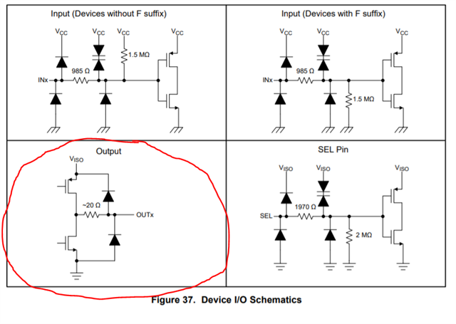
    edit 3: I had one more look into the datasheet of the isow7841. When I understand correctly, using multiple ISOWs builds some kind of voltage divider on the MISO_mcu lane (see Figure below, it's for the OUTPUT to the isolation, but I suppose its the same on the MCU output? Just with Vdd instead of Viso). If one OUT is set low and one is set high, I get a voltage divider, explaining why the voltage roughly halfs. So i would suppose that adding a third  ISOW (all with F-suffix) would cause an additional voltage drop to roughly 1/3. Am i correct? If so, I could fix the problem by adding some diodes into the MISO_MCU lane?

    edit 4: Just tested to add a third ISOW7841F and now we only get around 1.6V on the MISO_MCU lane. Shouldn't this be included into the datasheet? Some kind of "be aware when using more than one device in the same SPI bus"

    Best regards,

    Manuel

  • Hi Manuel,

    Thanks for sharing additional inputs and the waveform.

    thank you for your help so far! I can't confirm any low pull-up between MISO_iso and V_ISO, neither in the off state, nor in the on state (1.7 M). However, in the off-state, there are ~270k Ohm between MISO_iso and GND_iso, but in the on state the (measured) resistance drops to ~30 ohms! Is that a normal behavior of the ADS1220?  May this be the root of the trouble?

    My question of whether there is a low value pull-down resistor was to MISO_MCU line as the issue was observed on that line and not to MISO_iso.

    edit 4: Just tested to add a third ISOW7841F and now we only get around 1.6V on the MISO_MCU lane. Shouldn't this be included into the datasheet? Some kind of "be aware when using more than one device in the same SPI bus"

    Thanks for confirming this. It does look like you are connecting multiple outputs of ISOW together to connect to a single MCU input. Please note that no two digital outputs are supposed to be connected together. This is not specific to ISOW but applies to all digital devices including MCU and ADC unless, unless a particular device is specifically designed for special use cases, in which case, it would be explicitly mentioned.

    Please do share a larger schematic for review showing all the ISOW devices and their connection to MCU. Please do also refer to below FAQ on using multiple isolators for SPI isolation. Thanks.

    https://e2e.ti.com/support/isolation/f/isolation-forum/991655/faq-how-to-connect-spi-mcu-to-multiple-isolated-spi-nodes


    Regards,
    Koteshwar Rao

  • Hi Koteshwar,

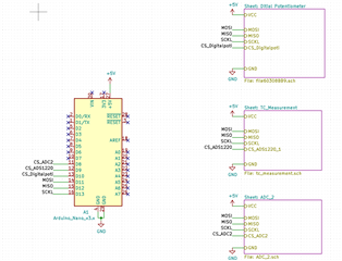
    thanks for your help again. You are right, I have two ADS1220 running on the same MISO, MOSI and SCKL. I think this works fine without the isolator, because the ADS1220 is designed for this use case and the MOSI goes into high-impedance state when CS is high? Here is the schematic:

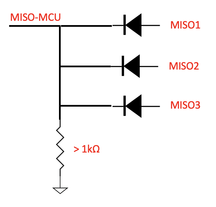
    Could I add a diode on each MISO_MCU line to block the LOW state of the isolators (with an lets say general 1k pulldown after the diodes)? Otherwise I would have to switch to the ISO7741 non-w version with the enable pin?

    Best regards,
    Manuel

  • Hi Manuel,

    Thanks for confirming.

    Yes, you can use diodes to connect multiple MISO lines together, as shown in the picture. Please make sure you use LDOs with low voltage drop-out and fast switching like the Schottky diodes. These external components will limit the maximum datarate that you can operate at, hence, will need to be chosen accordingly. Thanks.

    Regards,
    Koteshwar Rao