This thread has been locked.

If you have a related question, please click the "Ask a related question" button in the top right corner. The newly created question will be automatically linked to this question.

ISO1050: CAN output signal incorrect

Part Number: ISO1050

Dear sir/madam, 

I have been working on a CAN connection while using a PIC18F27Q84 with build in CAN controller and the ISO1050 isolated CAN transceiver.

When I programmed the pic it sends out a signal to the ISO1050, but the CAN output of the ISO1050 is incorrect. 

Here is a picture of it. The purple signal is the TX input of the ISO1050. The yellow signal is the CANH and purple signal the CANL.

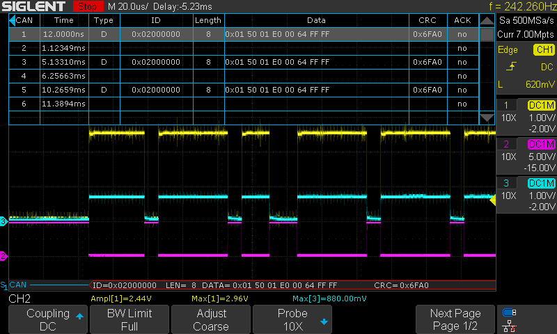
The voltage is always at 0V instead of the normal 2.5V and the CANH and CANL are not inverted from eachother. Also the recessive and dominant voltage are not correct. 

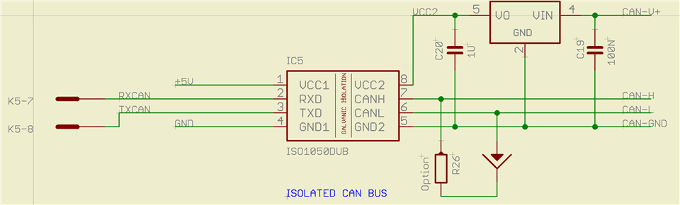
This is the circuit and R26 is the 120 ohm resistor for the CAN.

Any idea where I went wrong? 

  • Hi Jurian,

    Thanks for reaching out. I looked at the schematic and I do not see any issues while the waveform looks very unusual. Could you please confirm if you observed this behavior on only one device or multiple devices? If you have tested only one device, could you please replace this unit with a new one, test again and confirm?

    Please do test a new sample and let us know the results, thanks.


    Regards,
    Koteshwar Rao

  • Hallo Mr. Rao,


    Thank you for the reply!

    I have tested it with multiple devices. And all give the same results during the testing. 
    I have tried to place a 60ohm resistor on R26 to simulate the total CANbus resistance and measure it again, but without any different results.

    Kind Regards, 

    Jurrian Daenen

  • Hi Jurrian,

    As depicted in the plot, the voltage levels for CANH and CANL are not as expected. In recessive mode, the CANH and CANL voltages should be VCC2/2. There are three potential reasons that can cause the CAN bus to misbehave. First, power supply integrity in particular for Vcc2 in this case. Second, the CAN bus voltage was influenced by other CAN nodes. Third, you have a damaged ISO1050 device. To debug and find the root-cause, could you please try the following suggestion?

    1. Plot the Vcc2, GND2, CANH, and CANL by toggling TXD from 0 to 1.You should observe the recessive voltage to be (Vcc-gnd2)/2. Please make sure the Vcc2 meet the datasheet minimum specification.
    2. Does the CAN bus has other nodes? Any other CAN devices were driving the bus simultaneously? If so, could you please disconnect all other nodes and repeat your experiment.
    3. Disconnect all nodes and load from the CANH/CANL bus with no termination. Set the TXD to high, plot the CAN bus recessive voltage. The expected CAN bus voltage is Vcc/2.

    Regards,

    Alfred

  • Dear Alfred,

    Thank you for the reply.

    There was another device on the CANbus to make a complete CANbus and test my device. I found out that there was a problem with the CAN signals being connected to ground with a resistor which resulted in a faulty CAN signal. So I got it to work right now.

    Regards,

    Jurrian