This thread has been locked.

If you have a related question, please click the "Ask a related question" button in the top right corner. The newly created question will be automatically linked to this question.

ISO1212: Questions of VIH and VIL threshold

Part Number: ISO1212

Hi Team,

My customer is surveying ISO1212 and has few questions as following, please help to provide comments.

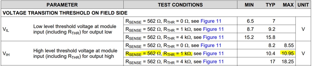
1. May I said that the tolerance of SENSE pin is 6.5V for VIL(min) and 8.55 for VIH(max), right?

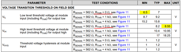
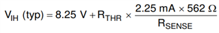
2. If the answer for Q1 is yes, the equation of VIH(max) should be 8.55V+1kohm*2.25mA*562ohm/562ohm ( use1kohm resistor as Rthr, 562ohm resistor as Rsense), right? Then the calculation result of VIH(max) is 10.8V but datasheet shows the VIH(max) is 10.95V. Please correct me if my understanding is wrong.

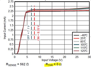
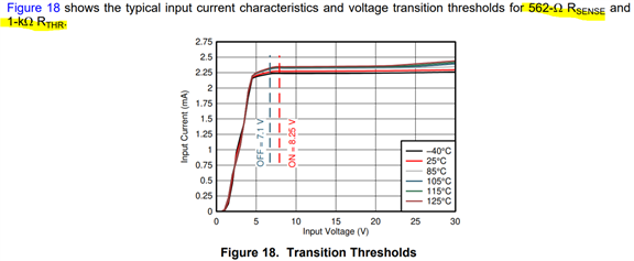
3. If Rthr is 0ohm, the calculation result of VIL(typ) is 7.1V, VIH(typ) is 8.25V, the result is different to the values shown in above table. Why?

4. Is there a same chart like below but the Rthr is 1kohm?

Thanks a lot.

Vincent Chen

  • Hi Vincent,

    Thanks for reaching out. Please see my inputs below to the questions you have listed out.

    1. The data shown in the table is electrical characteristics data. This means that this is the actual test data over a set of samples and the min/max values are statistical sigmas additions. This, in turn, means that any ISO1212 sample you pick should have its VIL and VIH thresholds within the char tables and should almost never hit VIL(min) and VIH(max) values, provided they are tested according to the conditions mentioned in the datasheet.

    2. The VIL(typ) and VIH(typ) equations that you see in the datasheet are the equations derived from the actual circuit. These are to help customer choose the right external components to set the thresholds to their requirement. Nonetheless, these are still theoretical calculations and the practical results could be slightly different due to the tolerances of external components including the resistors. If they are tested according to datasheet recommendations, then we expect them to b in the range of what is specified in the datasheet.
    Please note that these equations are only for typical threshold calculations and these might not hit the min and max values specified in the datasheet.

    3. Like I mentioned earlier, typical values of VIL as 7V and VIH as 8.2V in datasheet are actual test data observed on samples while the 7.1V and 8.25V values used in the equations from the actual circuit for theoretical calculations. Hence, the calculated values are not necessarily expected to match exactly with the typical statistical test values mentioned in datasheet. The calculated values are expected to be within the min-max range of datasheet specifications.

    4. Please allow me to check if we have such a plot for RTHR = 1kΩ. Thanks.


    Regards,
    Koteshwar Rao

  • Hi Koteshwar,

    Thanks very much for prompt response. I will reply customer based on your comments.

    Regrading question 4, I think I found the plot in datasheet.

    There is a one more question from customer just now. He is designing type-3 DI module, the VIH threshold is 11V.

    If customer choose 562ohm,1%, 1kohm,5%(since this 1k resistor is high watt one and most popular in customer side), can this combination let VIH(max) under 10.95V? 

    Thanks a lot.

    Vincent Chen

  • Hi Vincent,

    Thanks for the update.

    The plot in Figure 18 is the same plot as Figure 5, the reference RTHR = 1kΩ is a typo and will be corrected in the next revision of datasheet. Regarding your request for the plot for RTHR = 1kΩ, I am sorry we do not have such plot available to share for RTHR = 1kΩ.

    The above electrical characteristics table with RTHR = 1kΩ is for a resistor of 1% tolerance and the min / max values listed in the table are only applicable for 1% resistors. When a 5% tolerance RTHR is used, we expect the VIH(max) to be increased by 125mV, approximately. Please note this is only an estimation and not the actual char data.

    I understand customer has higher wattage 1kΩ running in high volume, one of the key benefit of ISO1212 is that it eliminates the need for high wattage resistors. Hence, if possible, please do request customer if they can use a lower wattage 1% resistor thereby saving some cost. Thanks.


    Regards,
    Koteshwar Rao

  • Hi Koteshwar,

    Customer is considering to use high wattage resistor or not, because high wattage resistor helps on module's robustness. It can prevent get damaged from unexpected touching AC power line in a short period. 

    There are two questions need your comment.

    1. Datasheet has EMS test result as below, the DUT doesn't have TVS, right? What is the wattage of RTH(1Kohm)? 2. Customer tested EVM(RTHR is 1kohm, RSENSE is 562ohm), when applying 5V on pin9 of J4. The current flow into RTHR is about 1.45mA. Is this value expected? That is why customer asks input current plot with 1kohm RTHR.

    Thanks a lot.

    Vincent Chen

  • Hi Vincent,

    Thanks for sharing additional information, please see my inputs below.

    1. Please allow me to check the actual wattage of 1kΩ RTHR resistor that was used for Surge testing and come back to you.

    2. With 1kΩ RTHR, VIL(typ) becomes 9.2V and the input current from 0V input upto VIL(typ) is going to be between 0mA and 2.25mA (regulated current for RSENSE = 562Ω). Since applied 5V is between 0V and 9.2V, a current of 1.45mA is expected, which falls between 0mA and 2.25mA.

    I understand Input Current vs Input Voltage plot for RTHR of 1kΩ would have helped customer here, unfortunately, I do not have the same to share with you. Please do note that by adding RTHR, we are only moving the VIL and VIH thresholds while the input current pattern is going to remain the same as of Figure 5 (with RTHR = 0Ω).

    Please let me come back to you on the RTHR wattage, thanks.


    Regards,
    Koteshwar Rao

  • Hi Vincent,

    Meanwhile, I wanted to share a tech note on surge testing for ISO121x. Please do share below tech note link to customer to show some of the Surge test experiments conducted with various RTHR resistors (along with part numbers) and their test results. Thanks.

    https://www.ti.com/lit/pdf/slla483


    Regards,
    Koteshwar Rao

  • Hi Koteshwar,

    Thanks a lot for sharing this tech note with us, it should be very helpful for customer.

    When you check the actual wattage of 1kΩ RTHR resistor that was used for Surge testing, could you also help check the TVS was installed or not.

    BR,

    Vincent Chen

  • Hi Koteshwar,

    Customer has lots of interest on this tech note, so R&D would consider to implement below protection structure. The surge pass criteria of customer's product spec. is +-1KV, but customer would have a margin for pass +-2KV when they perform surge test.

    So, could you please help comment which TVS part can achieve this performance if RTHR is a 1kohm, 5%, 1206 thin film resistor?

    Thanks a lot.

    Vincent Chen

  • Hi Vincent,

    Thanks for customer feedback.

    When you check the actual wattage of 1kΩ RTHR resistor that was used for Surge testing, could you also help check the TVS was installed or not.

    For the test results that are listed in datasheet, there was no TVS diode used / installed.

    So, could you please help comment which TVS part can achieve this performance if RTHR is a 1kohm, 5%, 1206 thin film resistor?

    Meeting 2kV Surge with a thin film resistor RTHR with the circuit shown in Figure 2 requires the RTHR to be capable to support 4kW of peak power. Peak power specification is usually not defined for thin film resistor and hence, it is difficult to choose a resistor. Customer will have to try out various wattage resistors to see what meets their requirement. Alternatively, if customer can choose MELF resistor then the resistor will be able to handle the peak power without any issues. Please refer Table 2 in the tech note for TVS diode part numbers used along with MELF resistor.

    If customer doesn't want to use MELF and only wants to use a thin film resistor then they can use the below circuit with the TVS diode part numbers listed in table below to meet upto 3kV of Surge. This circuit and test results are also provided in the Surge tech note.

    In this case, since Surge current is not going to pass through RTHR resistor customer need not choose a high wattage resistor here. Thanks.

    Regards,
    Koteshwar Rao