This thread has been locked.

If you have a related question, please click the "Ask a related question" button in the top right corner. The newly created question will be automatically linked to this question.

designing a CAN interface for automotive ECU from scratch

Other Parts Discussed in Thread: SN65HVDA542-5-Q1

Dear Sirs,

I am working on a new automotive ECU design, which shall be used on heavy duty Diesel powered engines.

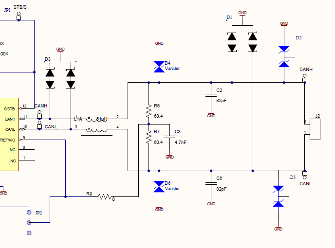
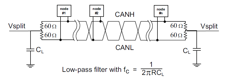
Among the features to build into it, one (or more) CAN interfaces are must.

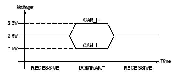
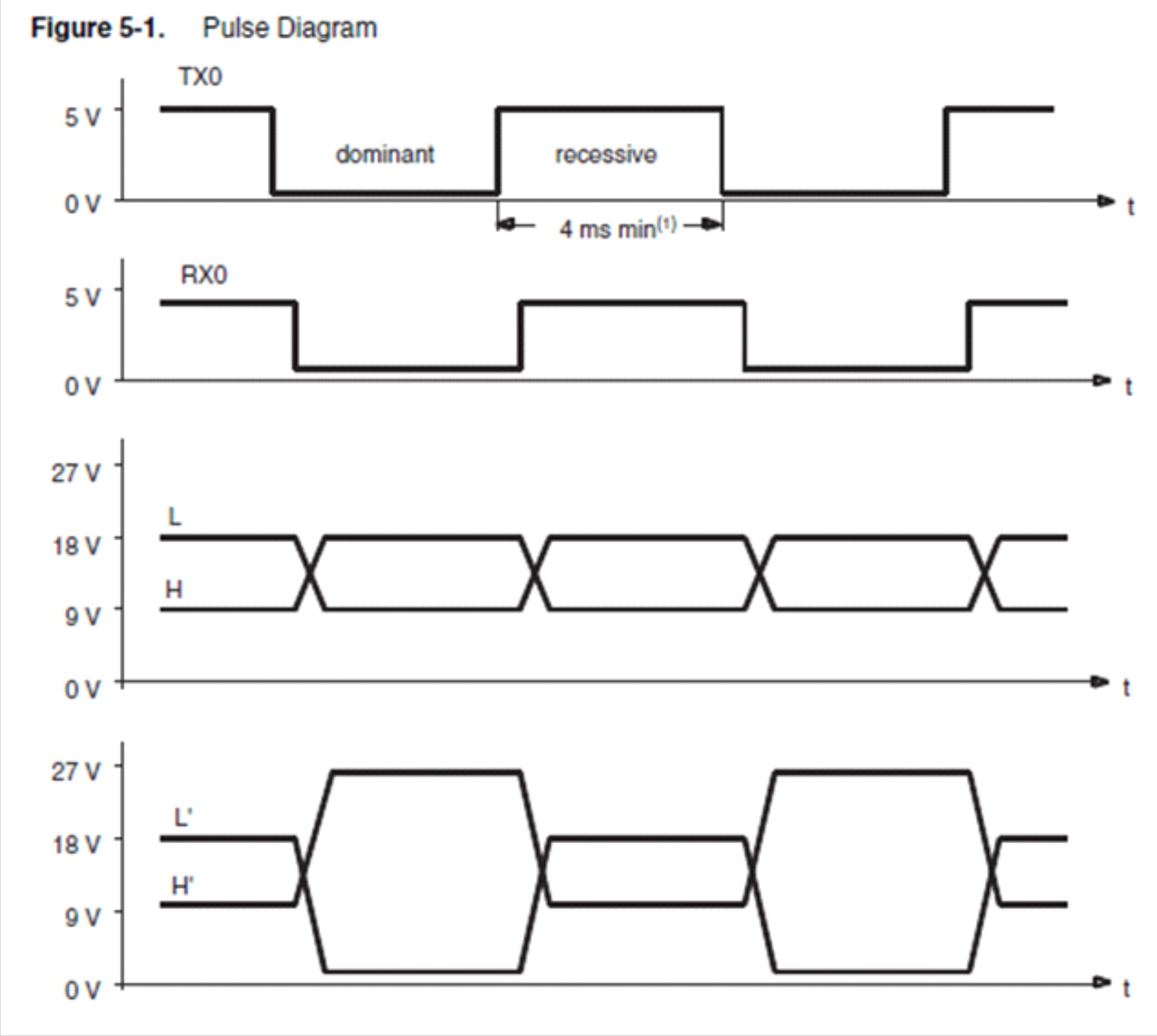
Looking at scope readings from other ECUs, we can see that the actual voltages used are about 9V(low) and 16V (high) levels. Baud rates are fairly low, at 125k, for this specific application.

A quick look into TI's product range indicated the SN65HVDA542-5-Q1.

I would kindly ask if this selection is correct and what external components would be required to get the voltage levels we need.

This would allow us to start designing as we purchase the parts. As it is not unusual to any of us, this is quite urgent.

Thanks in advance,

Daniel Sofer

DSA

  • Daniel,

    To start off, here is a comparison of the CAN devices that we offer. As you can see, depending on the low power mode you are looking for (standby, silent) and whether you are looking for a split pin or and I/O voltage level pin you will be looking at different devices. 

    HS CAN Device ISO11898-2 ISO11898-5 Low-Power State Wake I/O Voltage Split Pin
    HVDA1040A-Q1 Yes Yes Standby Yes 5 Yes
    HVDA1050A-Q1 Yes No Silent No 5 Yes
    HVDA540-Q1 Yes Yes Standby No 3.3/5 No
    HVDA540-5-Q1 Yes Yes Standby No 5 No
    HVDA541-Q1 Yes Yes Standby Yes 3.3/5 No
    HVDA541-5-Q1 Yes Yes Standby Yes 5 No
    HVDA542-Q1 Yes Yes Silent Yes 3.3/5 No
    HVDA542-5-Q1 Yes Yes Silent Yes 5 No

    The TXD and RXD pins can be interfaced directly with a micro, only requirement being that the pin that TXD is attached to has an internal pull-up resistor. If this is not the case then an external pull-up is required since the TXD pin is open drain.

    For the most part the only other design considerations that need to be considered are the type of external protection that you want to provide on the CAN bus pins. These protection schemes can vary from OEM to OEM. Below is a picture of a genaric CAN EVM that we have that enables uses to choose between have chokes, diodes, caps in different areas on the bus. 

    John

  • Dear John,

    I've had problems posting this reply, so I hope this one goes through.

    Low power mode is not a concern for our design, we shall shut down the ECU when engine is off, so just about any behaviour would fit our needs.

    As fas as protections are concerned, they may need to be tested, and for that much please point me to the link for the EVM you mentioned, should it be possible to purchase one.

    We shall certainly be working at 5V for I/O.

    As for split, what are the advantages?

    However, what I still have not understood is how the actual CAN bus voltages are generated. On the real, existing vehicle CAN bus (a heavy duty Diesel vehicle, with 24V electrical system) the CAN bus voltages are +9V (low) and +16V levels are generated. These are the voltage levels I must have in the CAN bus because our system will be plugged into the existing CAN bus.

    Thanks in advance,

    Daniel

  • Daniel,

    Unfortunately the EVM I was mentioning is not yet released, but we could work something out to get one populated in shipped to you if needed.

    The split pin offers some bus stabilization. The combination of the output 2.5 volt supply,  and the resistors and cap which make a low pass network, will help remove high frequency noise on the bus.

    What I do not understand it "the CAN bus voltages are +9V (low) and +16V levels are generated". A CAN bus has the following characteristics:

    Our tranceivers are designed to hold the bus recessive at 2.5 volts and have the dominant state create a ~2volt differential signal centered around 2.5volts. Please provide me more information on the CAN bus for your Deisel Truck application and I can be of more assistance. 

    John

  • Hi John,

    As far as the EVM, it would be of great help, of course. But maybe we can just work things out via posts and just select the correct component and proceed directly to making our own PCB, even if a development one to start with.

    Now, as for voltage levels: Indeed the physical reality of the CAN busses I've come across in heavy duty vehicles has quite different voltage levels than those you mentioned, most likely to withstand electrically harsh environments. The actual waveforms are something like this:


  • For some reason the waveform pic did not get posted. Here it is:

    Apparently this is according to ISO WD11992-1.

    All real life readings I've come across are +9/+16V.

    Cheers

    Daniel

  • Daniel,

    This is the first time that I have seen CAN bus voltages at these levels. TI does not offer any devices capable of this. We have some 3.3 volt and 5.0 volt CAN transceivers. 

    3.3 volt bus levels:

    5.0 volts bus levels

    Thanks,

    John