This thread has been locked.

If you have a related question, please click the "Ask a related question" button in the top right corner. The newly created question will be automatically linked to this question.

David Stanton PGA450 EVM GUI problem

Dear David Stanton,

My setup  and Error details:

All jumpers are connected as per default setting(User guide section 6.2).Also I have populated the R2 -0 ohm resistance, connected 8 V supply to power terminal, connected the TI GER board to the EVM and USB connected to PC. I have installed the GUI-1.38.32 and open my PC.

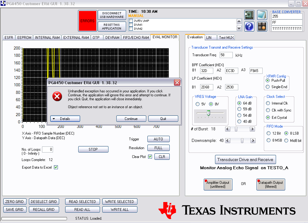
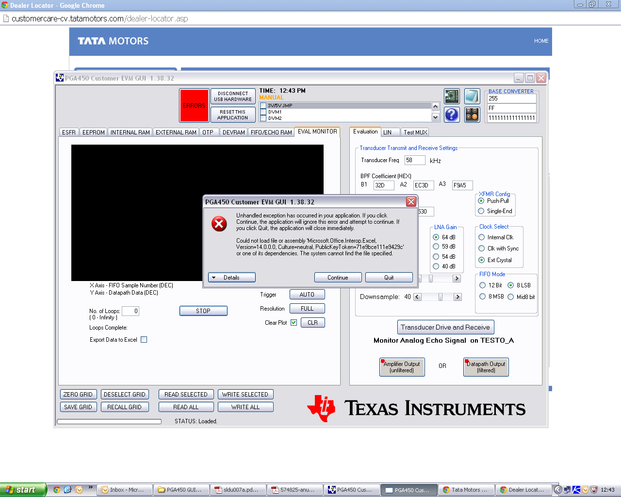
After that in ESFR window we click the OFF(MicroReset) and Press READ ALL button. Here we are getting some hex value in the table, then we press the ON(MicroActive) button and go to DEVRAM. Now, we Load the .hex file through DEVRAM (only "program DEVRAM through hex file and verify DEVRAM programming" check boxes are selected). The Error shown is DEVRAM Verification Unsuccessful. After that when I go to the EVAL MONITOR and set all the Evaluation parameters and Press "Transducers Drive and Receive" and then Press START button , we are getting a ERROR message as shown in the picture below :

Also we have seen that the 5 V is not available at test points. For more information please see the below image:

  • Hello Praveen,

    I believe David Stanton is no longer with TI; however, I have pinged the supporting apps engineer and they will respond back with an answer once it is available.

    Thanks and Best Regards,

    Wen-Shin Wang

  • 1.) After ensuring that the device is in reset, on the OTP tab, click on the "Check OTP Status" button.

    2.) If the OTP status is "empty", then continue with the steps below.  If it reads "OTP is Programmed to Jump to DEVRAM", then please let me know.  The first time an IC is programmed, several jump statements need to be programmed into the OTP.  You only need to do this once per IC.

    3.) Apply 8V to the VP_OTP pin, it sounds like you are already doing this since you installed R2.  Please note that you should not continuously apply 8V to the VP_OTP pin, so it would be better to remove R2 and use a jumper wire to apply the 8V this one time.

    4.) On the DEVRAM tab, check the "Program OTP Memory Also" checkbox.

    5.) Load the .hex file into the DEVRAM 

    For the evaluation tab error, do you have Office 2007 or Office 2010 i1050.PGA450 GUI 1.38.33.zipnstalled on your computer?  The GUI version you are using has a problem with Office 2007.  I've attached the corrected GUI.

    The 5V is generated from the TI-GER board, and is only needed for UART communication over RS232.  Is the jumper on the TI-GER board on 5V?  There might be an extra step you have to follow on the GUI to turn on the 5V, but I won't be able to check until next week.

  • Dear Clancy Soehen,

    Thanks for your valuable support.

    Now the GUI is working fine but we are facing problem in Export Data to Excel. When we click the  “Export Data to Excel” check box then we are getting Error as shown in below Screen shot:

    Also provide the following information:

    1. How to calculate the distance in feet or meter?
    2. How to configure the UART to send the distance information to PC? If we require any programming to configure the UART, please provide all the necessary information.
    Thanks,
    Praveen