This thread has been locked.

If you have a related question, please click the "Ask a related question" button in the top right corner. The newly created question will be automatically linked to this question.

CC2500 to CC2591

Other Parts Discussed in Thread: CC2500, CC2591, CC2530, CC2520, MSP430G2553, CC1101

Hello,

TI

We are trying to use two of your products.

1. CC2500
2. CC2591

This is my one of stating for RF design from scratch as i was originally working on modifying designs so please bear with me ..!!  

We are trying to interconnect these two.What I have questions about is following:

1. From one of your Reference design for CC2530 and CC2591 we are trying to do our layout But instead of CC2530 we are using CC2500.Since you already have a starting point in datasheet of CC2591 but is it necessary to put those 3 inductors and 2 caps in between RF_P and RF_N pins or we can go without it and get the output impedance.??

2. If we are using FR-4 material for the PCB manufacturing so is it going to be a problem since your reference design used DE104iML material which is not very commonly available??

3. If we are doing the design in two layers instead of 4 layers can you provide me the criteria or calculations that we have to do or guide me to any kind of calculator that can provide some sort of ideal for T-line length and  width and any other impedance matching traces.???(we can sacrifice in frequency slightly so that wouldn't be an issues as we are trying to prove at which extent it is going to work???)


Thank you in advance for your response.

Regards,
Devansh Shah

  • 1) From what I could find out the optimal load impedance seen from the RF_P/RF_N pins are fairly equal on CC2500 and CC2520. Therefore the CC2520+CC2591 (http://www.ti.com/tool/cc2520-cc2591em_rd) ref design is a good starting point. The network shown in CC2591 is just for illustration. The CC2591 is sensitive for the impedances seen on all pins and the reference design should be followed as close as possible.

    2) As long as the the FR-4 material used has close to the same Er as the material used in the reference design. Equally important is to follow the same stack-up as in the reference design eq the same distance between layers. I would strongly advice against trying to use a 2 layer PCB since the distance from layer1 to layer2 is very important and a solid ground plane is a requirement. Note that the ref design uses 3 line inductors that is very important to keep the layout of. If you have to do changes use ADS or similar to find the impedances on the ref design and on your PCB.

  • Hello!

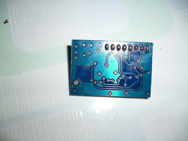
    I am building a car robot controler that use CC2500 and CC2591, but i have very short range tranceiver, it about 3 m.

    I think CC2591 not working, althought i connect PA_EN=1, EN=0 in TX mode, PA_EN=0, EN=1, HGM=0 in RX mode.

    Crystal is 26Mhz SMD C3225, MCU: msp430g2553.

    I need long range, about 300 m, someone help me?

    Thank you and best regard!

  • - Is this a 2 or 4 layer board

    - From the picture it looks like you don't have the maximum amount of vias under the RF chips, it should be at least 4 down to round from each chip.

    Apart from that I need schematic as pdf and layout as gerber to make further comments.

  • Thank for your answer!

    This is 2 layer board, board type: FR4, via size: 1.0mm, diameter of drill is 0.6 mm.

    and this is schematic of my project:

    if via under chip pad not enought, i think the distant tranceiver  atleast 10 meter. But i only transmit data with 1 meter distant is maximum. 

    I design look like this with cc1101, bank frequency is 433 Mhz, every thing so good, distant is about 70 meter.

    What's wrong with my schematic and layout?

    Thank you!

  • For a design using a FEM (as CC2591) it is highly recommended to use a 4 layer board. Good ground to the RF chips are important.

    I notice that your schematic is nowhere close to the recommended reference design I linked to in a earlier post in this thread.

    To do a design with a FEM it is highly recommended to use a spectrum analyzer size you have to measure harmonics etc in addition to the fundamental.