This thread has been locked.

If you have a related question, please click the "Ask a related question" button in the top right corner. The newly created question will be automatically linked to this question.

SN74LV8154-EP: Realizing 32 bit counter from 16 bit; wrong voltages.

Part Number: SN74LV8154-EP

Hi, 

I'm using a dual 16 bit binary counter SN74LV8154-EP. I need to enable the 32 bit counter feature, and I'm having problems with that. And I'm also having weird outputs. I would really appreciate some help!

Please see an image of the circuit attached.

VCC for the counter is 3.04V. Input oscillations are between 0.4V and 2.4V (20MHz oscillator). First I took Yn readings from counter A, and it works correctly except for the fact that output voltages are wrong. I'm supposed to be getting 0.48V for LOW and 2.48V for HIGH according to the data sheet, but I'm getting ~0V to ~1.8V. Why? That's my first question.

And I'm taking very strange Yn readings from counter B. 20MHz between -0.18V and 0.18V. The data sheet specifically states that "A 32 bit counter can be realized by connecting CLKA and CLKB together and by connecting RCOA to CLKBEN." I did that. Byte selection inputs are all correct too. It's not always LOW – I'm using a 20MHz counter, I'm supposed to observe oscillations. But for some reason it doesn't work. What am I doing wrong? And how do I solve it?

Thank you very much in advance!

  • I'm using RIGOL DS1102E oscilloscope to read the data. 1x probe.
  • Savva,
    Before worrying about operation as 32bit counter, lets make sure device is functioning properly.
    From your description, it sounds like there is an issue.
    Can you provide scope shot of the inputs and one of the Y outputs?
    Seeing only 1.8V for an output high is definitely an issue. Do you have any load on this output other than oscope? Is scope probe high impedance or 50ohm terminated. With 50ohm termination, you would get significantly attenuated output.

    Additionally, the power up state of the device is not guaranteed. Usage of the clear to initialize and clear counters in recommended after power up.
    Regards,
    Wade
  • I I found out the reason why I'm getting wrong Yn voltage outputs – it's cause Vcc is not 3V. But I don't understand why it isn't. I've got a 3.3V source and I use a voltage divider to get it to 3.04V. However, once I connect 3.04V line to the counter's Vcc, the voltage in it drops to 1.8V. How? Why? I don't understand.

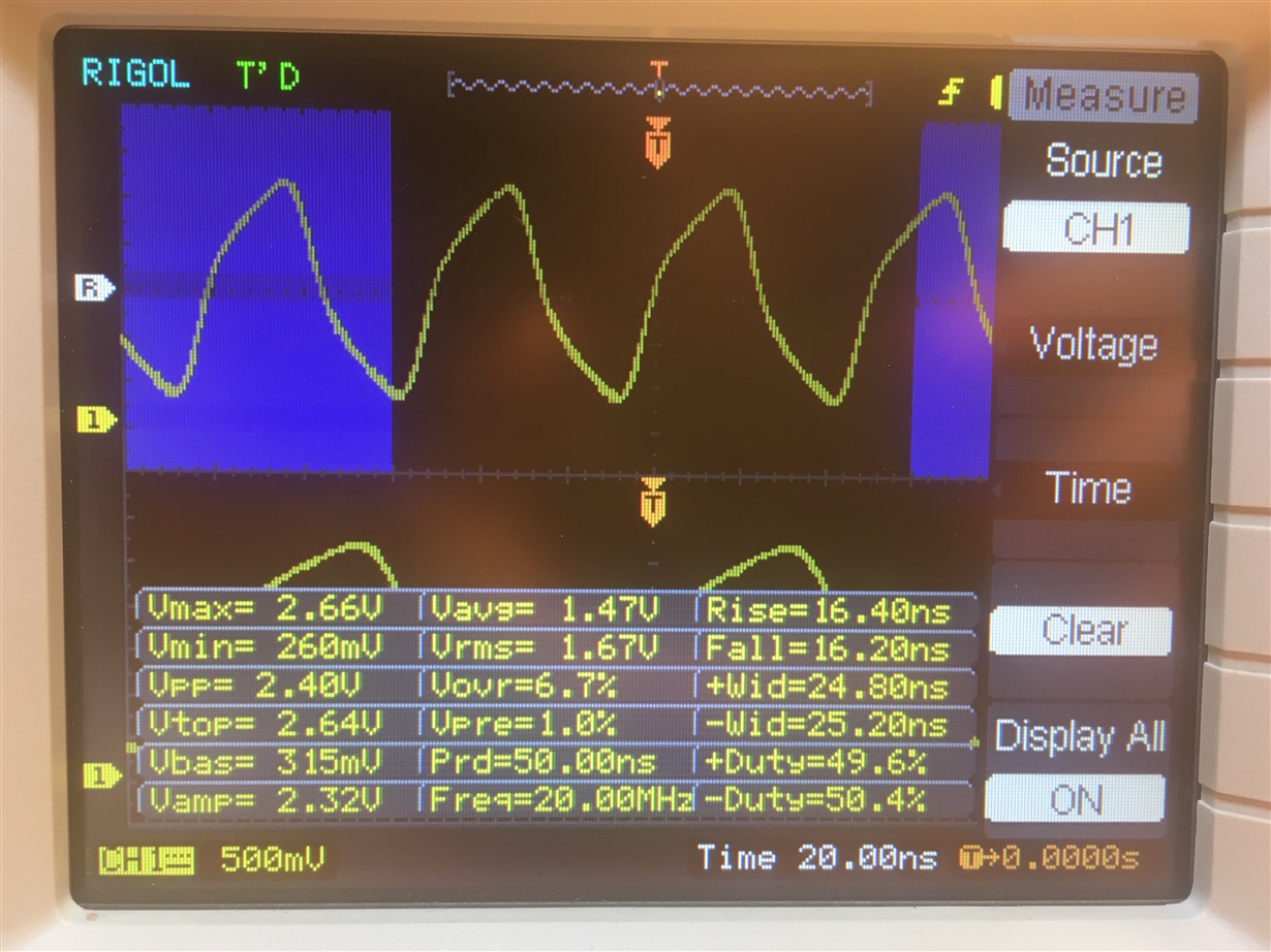
    I attached images: my input pulse, my Yn output pulse for A counter, my Yn output pulse for B counter, and my supposed-to-be 3.04V voltage source when connected to the counter's vcc. 
    DMM readings are the following: 1.46V for input pulse (thats sound about right: about an HCMOS oscillator that's supposed to produce 0.4V to 2.4V), Vcc input before attaching the counter: 3.04V; after: 1.75V. B counter's Yn outputs: 1.2mV.

    I'm using RIGOL DS1102E oscilloscope and Rigol's RP2200 passive high resistance probe at 1x attenuation. Therefore no load except for that of the O'scope.

    I still have no idea why the B counter doesn't work.

    Also, I didn't quite get what you meant here: "Additionally, the power up state of the device is not guaranteed. Usage of the clear to initialize and clear counters in recommended after power up."

    Thank you for your answer!

  • Forgive me for the lack of clarification for the images. 1st one is the A counter's Yn outputs. 2nd one is the B counter's Yn outputs. 3rd one is my clock pulse. 4th one is the weird vcc I'm getting when I connect 3.04V source to the counter.
  • Let's solve one issue at a time.

    First major problem is lack of proper supply.   What does your voltage divider look like?  

    This is not a great solution, as the current demand from the counter is dynamic.  This dynamic current will cause the voltage seen at VCC to change. 

    The divider current would need to be high enough that the dynamic current component from counter is much less.  This is very inefficient.

    For testing purposes, it would be best to connect directly to supply.

    Is this on a breadboard, or PCB?   What decoupling do you have on VCC? 

    With respect to power up state.  After device is first powered, the counter values are not deterministic.   They could be 0s, 1s, or combination.  Only guaranteed way to insure their value is to assert clear after power up.

    Regards,

    Wade

  • Savva,
    Were you able to get better results with improved power?
    If this resolved your issue, please click "This Resolved My Issue" on the forum.
    Thank you.
    Wade