(assuming Chris Hall is answering)
hi Chris, I'm having some trouble understanding the timing when in pulse-sync mode, specifically Tdr.
assuming that Fclk=3.125MHz and Sclk=1.5625MHz:
once I assert the SYNC pin, DRDY goes high and then it will go low again after a period of Tdr. According to section 7.7, Tdr depends on which filter you're using, the sample rate, and the clock rate.
so if I'm only using the SINC filter with the default data rate of 32kSPS, then Tdr=968/3.125E6 = 310us. is that correct?
if I'm using the SINC + FIR filter with the default data rate of 1000SPS, then Tdr= 63/1000 + 466/3.125E6 = 63ms. is that correct? Section 7.7 gives Tdr for Sinc and FIR individually. should I add them together if in SINC+FIR mode?
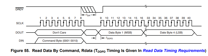
Assuming SINC filter only, the SYNC pin is asserted, then Tdr time passes and DRDY goes low, then I take 32 Sclks to send the RDATA command, and then according to section 7.9, it will take another 1/Fdata for Tdr to go low again, then I take another 32 Sclks to read the data in. so the total time would be ~(1.28us + 310us + 20.48us + 31.25us + 20.48us) = 383.49us (SYNC + Tdr + RDATA + Tdr + DATA)
is that correct?
(all of the numbers in the datasheet seem to assume that Fclk=4.096MHz. what if it's not?)