This thread has been locked.

If you have a related question, please click the "Ask a related question" button in the top right corner. The newly created question will be automatically linked to this question.

SN74AHC245: Input to Output delay time (tPHL and tPLH)

Part Number: SN74AHC245

Hi Team,

I want to check the tPLH and tPHL parameters in datasheet. I find below table in datasheet. It seems like that the parameters is related to Vcc and Cload on PCB trace.


Below is our measurement. We measure the SN74AHC245 pinout directly.(Input & Output) The delay time is around the 10ns. It can meet the max value showing in datasheet, but we measure the pinout directly. Does it mean that our Cload is much smaller than 15pF?
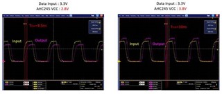
And below is my questions.

1. From our test result, is it make sense to you

2. How could we define Cload? Equivalent cap on PCB trace? If we measure the pinout directly, can we say Cload = 0?

Roy

  • Hi Roy,

    First, your probe will have some capacitance - even the best probes usually add 1pF, while typical ones can add 18pF. That's part of the load you're measuring.

    The trace will have some capacitance associated with it (as will any conductor connected to the trace). There are calculators available for determining the capacitance based on your PCB parameters.

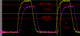
    Your scope images are very low quality - I can't really see any details, but it looks like you might be measuring rise time instead of propagation delay -- tPLH is the time from the input's rising edge at 50% VCC to the output's rising edge at 50% VCC. At 2.8V supply, the measurement point would be at 1.4V, for both the input and output signal.

    Can you post a higher resolution scope shot of the same thing, and an image of your PCB layout?

  • 2.8V tPHL : 

    2.8V tPLH : 

    3.8V tPHL : 

    3.8V tPLH : 

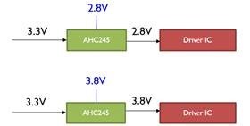
    Our structure

    Our layout trace cap estimation is 1.5pF. 

    Can you let me know how could we estimate the total Cload in our application?

    We want to estimate the max and min tPLH/tPHL in our application.

    Roy

  • Make sure to measure from 50% VCC to 50% VCC. It looks like you're measuring from 50% of the signal size, not 50% of the supply value.

    Total load capacitance is just the sum of all connected capacitance.

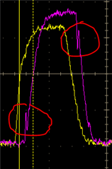
    It looks like you have some effects from ringing as well:

    This is likely due to the extremely light load, but could also be caused by relatively long traces. 

    Given the time scale, it looks like this is only 1 or 2 ns after the switching event, so it could be a reflection.

    We want to estimate the max and min tPLH/tPHL in our application.

    Since you're operating at 2.8V to 3.8V and the datasheet spec applies to 3V to 3.6V, you're going to see some variation in timing beyond the datasheet spec. The worst case will be at 2.8V, as lower voltages will always result in slower output signals. Since this is not a linear function and we don't have data at lower voltages, then I'm afraid I don't have a good solution for you to estimate the worst case. I would recommend to just add 30% to what you're measuring to give some headroom.