This thread has been locked.

If you have a related question, please click the "Ask a related question" button in the top right corner. The newly created question will be automatically linked to this question.

SN74HC595: SN74HC595 Current Consumption

Part Number: SN74HC595
Other Parts Discussed in Thread: SN74LV595A, SN74AUC244, SN74LVC541A

Hi good evening,

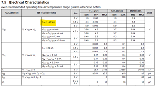
We tested the SN74HC595N for a VCC of 2V and were not able to get consistent current consumption per the datasheet.

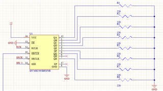
We used a load resistor of 220 Ohm and got a voltage drop of approx. 1 V. We suspect this voltage drop is too large and suspect there is some internal resistance.

So the following questions are:

1. How large is the internal resistance of the Q_A-H outputs?

2. What test condition was used to get the -20 uA current draw.

3. Why are we seeing a large voltage drop?

Please use the schematic below for reference, thank you.

  • 1. At 2 V, the worst-case resistance is 0.1 V / 20 µA = 5 kΩ.

    2. The load is a constant current sink of 20 µA. Then VOH is measured.

    3. Because the load is larger than 20 µA. (For currents larger than the specified IOH, the resistance is no longer guaranteed and also gets larger.)

    The SN74LV595A has somewhat stronger outputs, but at 2 V, its limit is 50 µA. You need to add a separate low-voltage buffer like the SN74AUC244 or SN74LVC541A.

  • Hi Russ,

    While Clemens is correct, I just wanted to add that the expected typical output impedance at 2-V supply is around 50 to 70 Ω. The datasheet spec is heavily guard-banded on the low current V_OH and V_OL specs for most logic devices, so the resistance that is calculated from the datasheet (5kΩ) is much worse than what would be seen in operation.

  • Hi Clemens and Emrys, thank you for your comments. We did a make prototype of the above circuit, but we replaced the resistor with the PIN diode we want to use and took some voltage and current measurements. The Vcc is 2V and we got 4.5mA of current and a voltage drop of 1.2V on each output pin of the shift register. So, our main concern is that is it okay to keep operating the shift register at such a high voltage drop because we are getting the desired current value we need at each output channel.    

  • Hi Aditya,

    The device can support up to 35mA per output, and up to 70mA total, so 4.5mA per channel is no issue.

    The only concern I would have is that the diode won't directly limit current, so if you make this a production design, ie thousands of systems are built, you may find that some devices have stronger outputs than others due to process variations, and perhaps some systems have a larger supply than 2V (not uncommon to see variations), and any increase in supply will increase drive strength at the outputs as well - ie you may see some systems going past that 70mA limitation and failing. I can't make any guarantees that every device will always work the same way the ones you have -- they are only designed to meet the datasheet spec under all conditions, and it doesn't provide a short circuit current at the outputs.