This thread has been locked.

If you have a related question, please click the "Ask a related question" button in the top right corner. The newly created question will be automatically linked to this question.

SN74AHC1G09: SN74AHC1G09 Output is not stable

Part Number: SN74AHC1G09

Hello,

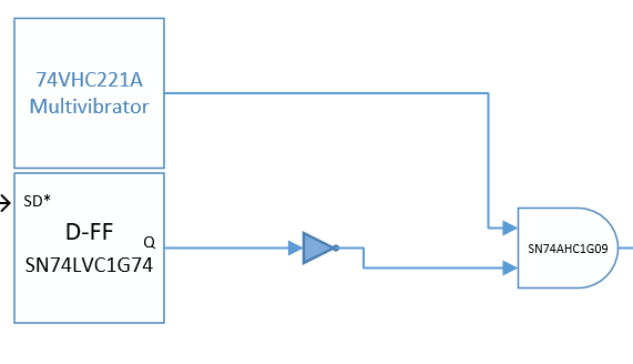
We are trying to use SN74AHC1G09 open drain AND gate in our design.

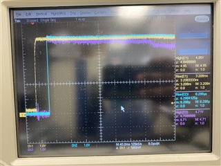
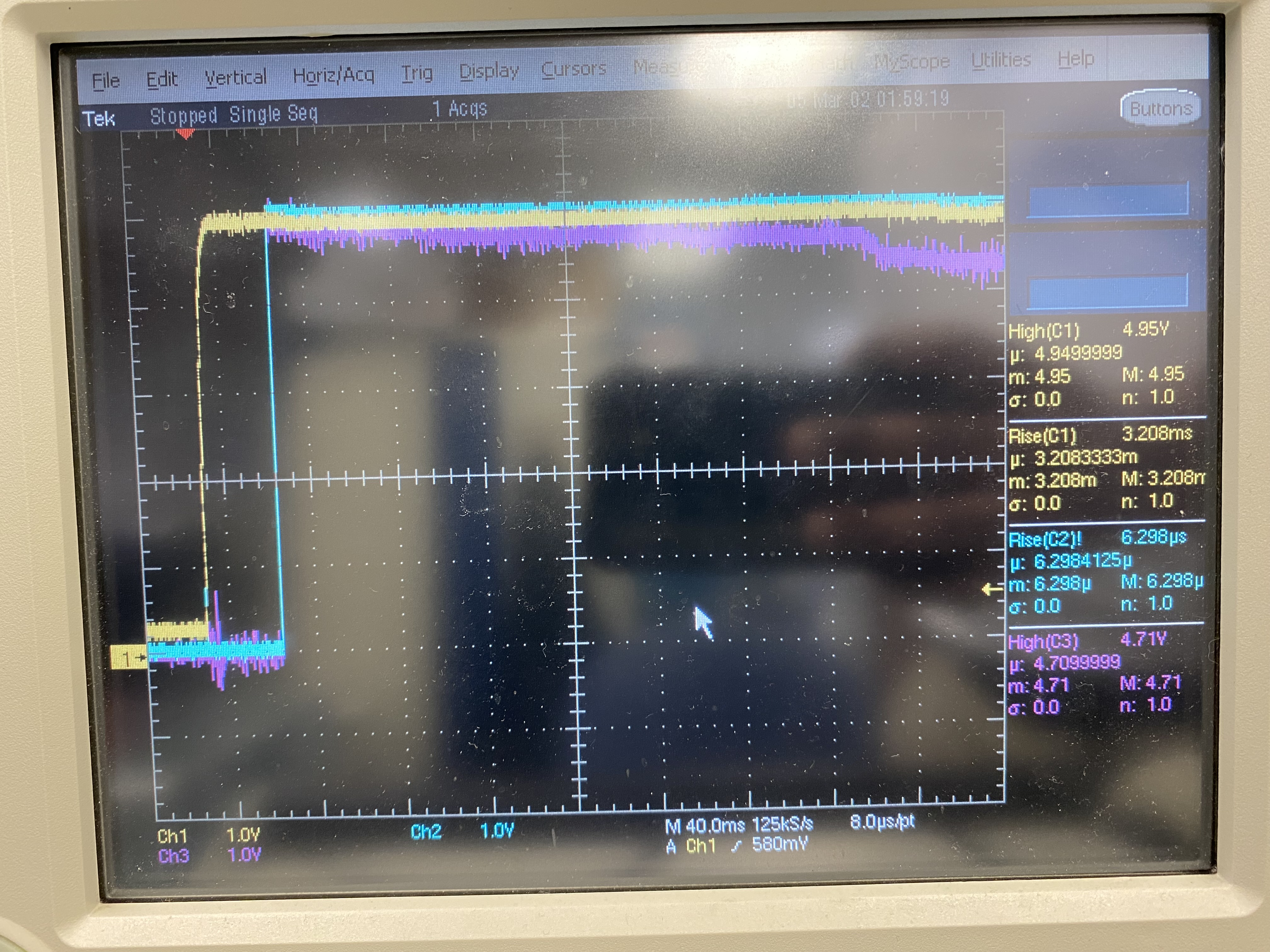
The Output of the device is NOT stable. It is Fluctuating and dropping down to 1V even though the Inputs are at High state.

The device operating at VCC- 5V and the inputs are at 5V logic ,Output is Pulled high(5Vcc) through 10K resistor.

Could anyone tell us why the device not working properly.

Regards,

Samson

  • A current of 0.4 mA flows through the resistor. It could be possible that the output is damaged (probably due to overcurrent or overvoltage), but might there be any other load on the line that pulls it down?

  • Hi Samson,

    Can you provide a complete schematic and oscilloscope captures of the issue?

    It would be best if I can see the supply, input, and output signals all on the same scope shot, preferably at a 100ns/V or smaller time scale.

  • Hi, Emrys,

    Thank you for the reply. Please find the attached waveform.

    Probe 1(Yellow) Input1

    Probe 2(Blue) Input2

    Probe3(Purple) Output

    Regards,

    Samson

  • Hi Clemens,

    Thanks for the reply.

    No, there is no load connected to output. 

    Regards,

    Samson

  • Hi Samson,

    Can you show your circuit setup?

    No, there is no load connected to output. 

    You mentioned a 10k pull-up resistor. How is that connected to the device?

    It looks to me like you may have a bad connection somewhere.

  • Even when the circuit was connected to load, we could see the same waveform. So we have isolated the load for verifying.

    Since this is open drain gate, we have pull up resistor at output and checking.

    Regards,

    Samson

  • Hi Samson,

    Can you show an image of your circuit setup? How is it connected?

  • Hi Emrys,

    Here is the outline of the circuit.

    This circuit is for Power button circuit for PMIC. In Earlier design we have used only Non-retriggerable multivibrator, and now in parallel to that circuit we are trying to add D-FF circuit for the long press shut down requirement.

    Here are the conditions:

    - The board should boot for the normal Power button press. 

    - The board should power off when there is long press of power button.

    Regards,

    Samson

  • Based on the lack of an actual schematic and your not wanting to show an image of the device / board -- there's likely not much I can do from my end to help you. I haven't even seen details of your load or a clear scope shot showing an issue. I expect this is a system-level problem that you need to troubleshoot.

    I suspect you know already, but just as a reminder, TI is one of the largest manufacturers of analog ICs in the world, with many billions of units shipped and an extremely low failure rate due to our excellent quality control and testing procedures.

    Every logic device we ship is tested for all DC electrical characteristics, and each lot is tested for timing characteristics. The device worked correctly per our final test when we created it - otherwise it would not have been packaged / shipped.

    I have personally been supporting logic devices for over 8 years, and I can only name one or two cases out of thousands that I have seen a device failing due to an issue from TI. In the vast majority of cases, it is a mistake from the user / system designer. I would be happy to help you troubleshoot, but I need your full cooperation.

    If you believe the TI device SN74AHC1G09 is truly faulty - you can start a return through your supplier, assuming they are a TI approved vendor. When doing this, you will need to provide a complete schematic, showing all input, power, and output connections. You will also have to clearly identify which datasheet specification is failing - or the return will be denied.

  • Hi Emrys,

    I totally agree with you. And we have used Number of TI parts in our design and we know how TI parts works. 

    We don't have schematic yet with this new implementation. we reworked externally. Hope you didn't receive the waveforms which i shared yesterday?

    I will check again any issues in system level.

    Here is the waveforms

    Probe 1(Yellow) Input1

    Probe 2(Blue) Input2

    Probe3(Purple) Output

    Regards,

    Samson

  • Hi Samson,

    Yes, I responded to this waveform with the following:

    It looks to me like you may have a bad connection somewhere.

    There is a great deal of noise on output signal, which is my first indication that the connection is not good, and the fact that it is drifting downwards tells me there is something else going on in the circuit.

  • Hi Emrys,

    We have checked our connections and see some issue at circuit level. we rectified and the part works fine.

    Thank you for your support.

    Regards,

    Samson

  • Hey Samson,

    I'm glad you were able to get it figured out. Please come back any time.