Other Parts Discussed in Thread: SN74LVC2G07
Good day,
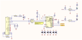
I have the following schematic used to communicate with a GSM module which provides the 1.8V.

When I Power the device the two LEDs LD1 and LD2 are off as they should be, but when I send a command and the LEDs are toggled, I can see the input at both pin1 and pin5 of U5 goes low and back high, but the outputs at pin4 and pin6 remains low.
I've found that touching any pin with my multimeter switches the output high.
I've added a decoupling cap of 100nF to U5 which isn't shown on the schematic. But it still doesn't work.
On the layout side, the Ground pin is connected to the ground plane on the bottom layer through a via close to the pin.
Any suggestions on how to fix this issue, or how to debug it further?

