Because of the holidays, TI E2E™ design support forum responses will be delayed from Dec. 25 through Jan. 2. Thank you for your patience.

This thread has been locked.

If you have a related question, please click the "Ask a related question" button in the top right corner. The newly created question will be automatically linked to this question.

CD4536B: How to generate a square wave with duty cycle of 70%

Part Number: CD4536B
Other Parts Discussed in Thread: TPL5110, SN74HC112, SN74LVC1G97

Hi,

I'm trying to use a timer IC to generate a square wave with a period of some seconds and a duty cycle of about 70% (or 30% and then inverting it).

I would like to use just HW, without a MCU.

The best IC I found to do this, I think, is the CD4536B, but studying the datasheet I didn't figure out how to generate a larger pulse width.

Is there any other IC that I can use at this scope?

Thank you in advance.

Best regards,

C.

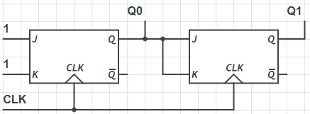
  • Would 75% be OK? If yes, try generating pulses with the TPL5110, building a two-bit counter with two flip-flops (e.g., SN74HC112), and then using an AND or OR gate to have the output active only in one of the four states. (Alternatively, it would also be possible to use one output of a four-bit shift register, which would require four D flip-flops with invidiual set/reset inputs to initialize them.)

  • TPL5110 is a good choice. 

  • Hi guys, thank you both for the help.

    Sorry for my late replay, I was thinking about this solution.

    My doubt is on the propagation delay of the flip-flops, which wolud cause the AND output to rise for few hundreds of ns also at the end of the high semi-period of the 2nd FF output

    Clk    ________---________---________---________---________---___

    Q1    _________----------------__________----------------__________-------

    Q2    __________--------------------------------____________________-----

    AND __________--------------__________-____________________-----

  • JK flip-flops allow you to build a synchronous counter.

    At 5 V, the propagation delay of the SN74HC112 is about 15 ns; the jitter for the two flip-flops on the same die is much smaller, typically less than 1 ns. This is smaller than the rise/fall time of the output.

  • Sorry but it doesn't add up to me.

    For the flip-flops at 3.3 V I see a propagation delay up to 100-200 ns.

    While for an AND gate the tipical propagation delay is up to 5 ns.

    This means that when Q1 rise at the end of the high semi-period of Q2, there could be up to about 200 ns in which both Q1 and Q2 are high, thus the AND output is high also.

    Where is the error in this thought?

  • So you intend to use a 3.3 V supply?

    In a synchronous counter, the flip-flops switch at the same time.

    If you want to slow down the AND gate, use a gate with Schmitt-trigger inputs (e.g., SN74LVC1G97) and add R-C filters at its inputs.

  • Yes, I have a 3.3 V supply.

    In that configuration the two FFs don't switch at the same time, because the output of the first FF is used as the clock input for the second FF. So there is a propagation delay between the two outputs.

    I thought about using an AND with Schmitt-trigger inputs, but I didn't find one with such an input hysteresis time.

    Maybe the RC filter is the only way, I was thinking about it.

    Thank you

  • In a synchronous counter, the FFs use the same clock:

  • Sorry, I was so confused.

    Thank you Clemens