Other Parts Discussed in Thread: SN74HCS165
Hi TI Teams,
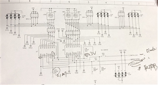
Can you help to check is there any problem for the SN74HC165DR schematic?
Thanks,
Kind Regards
Original question:

Hi TI Teams,
Can you help to check is there any problem for the SN74HC165DR schematic?
Thanks,
Kind Regards