This thread has been locked.

If you have a related question, please click the "Ask a related question" button in the top right corner. The newly created question will be automatically linked to this question.

TAS2505EVM: Unable to function properly, is it a hardware issue?

Part Number: TAS2505EVM
Other Parts Discussed in Thread: TAS2505

Hi Ti team,

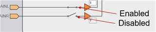
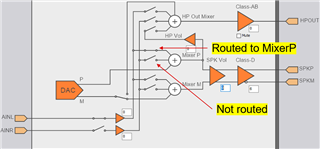
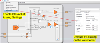
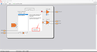
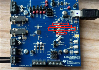
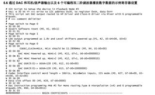
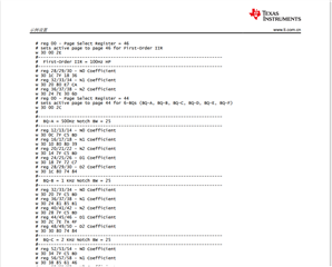
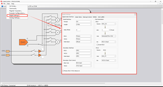
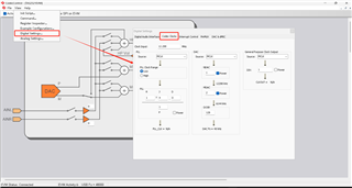
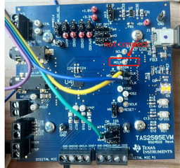
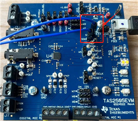
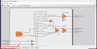
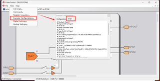
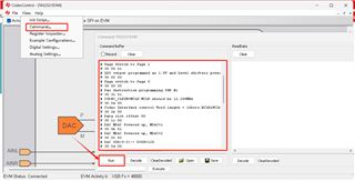
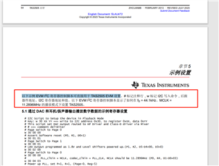
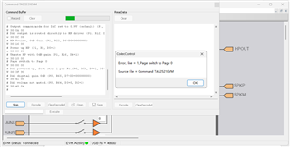
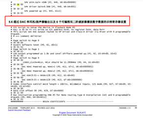
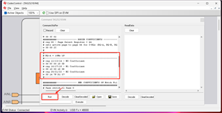
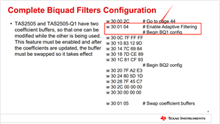
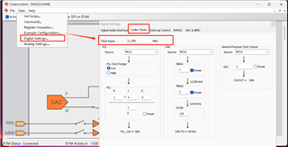
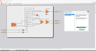
After connecting the TAS2505EVM board to the computer, I opened the Codec Control software, which displayed the connected device, and then clicked View ->Example Configuration... -> The progress bar on the Playback Class-D Speaker ->Program Codec software has been loaded (my understanding is that completing the above operation means completing the register configuration of the chip). Then, I connected a speaker to the output of the TAS2505EVM board and connected 100Hz and 10KHz sine wave inputs to the analog input, but the speaker did not respond.


Question: How should I configure Codec Control software debugging?
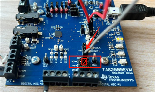
Question: How to connect the input and output interfaces of the TAS2505EVM board to drive the board?
I downloaded the file "TAS25xx Codec Control EVM (Rev. A)" from the TI official website and have reviewed it in detail, but I still haven't understood it. There is too little information online. Your company's professional technical personnel can explain how to drive this evaluation version

In my opinion, after the instance ProgramCodec is installed on the software, the register configuration of TAS2505EVM is completed. Whether I input audio signals through analog or I2S digital inputs, there should be sound coming from the output end, but my speaker has not responded at all

Thanks & Regards

  • Hi Yazhi,

    What is the analog input connection to the device? Are you using 2 different signals, one for AINL and one for AINR? Or only 1 signal in differential mode?
    From your description, you didn't enable the analog inputs, then you also have to route the analog signals to the Class-D driver:

    • For single-ended input on AINL: enable AINL, route AINL to MixerP or MixerM, unmute SPK output and enable Class-D.
    • For differential input across AINL/R: enable both AINL and AINR, route AINL to MixerP and AINR to MixerM or AINL to MixerM and AINR to MixerP, unmute SPK output and enable Class-D.

    For the digital input test case, you should be OK by just configuring the device using the "Playback Class-D Speaker" Example Configuration. Once that is completed, you should be able to play audio through USB.

    Best regards,
    -Ivan Salazar
    Applications Engineer

  • Hi Salazar,

    Thank you very much for your reply. I connected the analog input of the device to a 100Hz sine wave output by the microcontroller DAC, and only used an AINL signal. After setting the software according to your instructions, the output speaker can play the sound of a sine wave, which proves that the hardware of the TAS2505EVM evaluation board should be fine.
    Next, I would like to ask you other questions. As you mentioned earlier, if you want to test digital input, you only need to use the "Playback Class D Speaker" example configuration, click on ProgramCodec, and the progress bar will be loaded. There is no need to perform operations such as "fluctuation switch control, unmute SPK output, and enable Class D" like simulation testing, right?
    That is to say, after clicking the "ProgramCodec" button, I have completed the configuration and do not need to make any other settings to the CodecControl software, right?

    In my system, I want to use a microcontroller to provide digital signals to TAS2505EVM through the I2S interface. When my software uses the "Playback Class D Speaker" example configuration, do I only need to connect these four IO ports on the board? Do you need to make any other connections for the four interfaces marked in the figure?

    Thanks & Regards

  • Hi Salazar,

    I just tested connecting my audio input module (the audio input signal is a microphone module with an I2S interface) directly to the I2S interface of the TAS2505EVM evaluation version (DIN, BCLK, and WCLK pins), opening CodecControl software, downloading the "Play D-Class Speaker" example configuration, unmute SPK output, and enable D-class. The output speaker has normal feedback sound, but I am speaking at the microphone, The speaker only has corresponding ground vibrations and cannot transmit human voices. The microphone module I am using has 24 bit I2S data. Is the data format not configured correctly? 

    There is another question: I consulted the chip manual of TAS2505 and found that TAS2505 has 6 programmable second order filters internally. However, the "Play D-Class Speaker" example configuration downloaded from CodecControl software does not configure the registers of the programmable second order filters. If I want to use these 6 programmable second order filters, how should I configure them?

    Looking forward to your prompt reply.

    Best regards,

    Yazhi

  • Hi Yazhi,

    Using the test points on the EVM to connect an external I2S source is OK, however, the onboard controller (TAS1020B) is still operating and connected to the same signals.
    I'm guessing your I2S-mic module works as slave on I2S interface, similar to TAS2505, and both your module and TAS2505 are using TAS1020B clocks to operate. If that's the case, perhaps the DIN from TAS1020B is causing some interference with the mic module. You can try by disconnecting DIN from TAS1020B by removing W8, then use the middle pin from that same header to connect the Data from your mic module.

    Regarding the biquad filters, first please make sure you're using the proper processing block "PRB_Px" if you need 3 or 6 bands. Then you can calculate the coefficients using the TIBQ tool: https://www.ti.com/tool/COEFFICIENT-CALC Make sure to set the coefficient resolution to 24-bits (default is 16-bits).

    Best regards,
    -Ivan Salazar
    Applications Engineer

  • Hi Salazar,

    Following your suggestion, I removed W8 to disconnect DIN from TAS1020B, and then directly connected the data cable SD of the microphone module at the digital audio input end to pin 2 of W8. This means that the data cable of the microphone is directly connected to the TAS2505 chip. The result is that compared to the previous connection method, the noise from the output end speaker is basically eliminated, but still no human voice can be heard.


    The overall effect of the device now is: I blow air at the microphone, and the output speaker can play a perfect blowing sound. However, when I speak at the microphone, the output speaker cannot play anyone's voice. I guess it's because the TAS2505EVM evaluation version automatically filters out the low-frequency human voice? How should I solve this problem?

    Looking forward to your prompt reply.

    Best regards,

    Yazhi

  • Hi Salazar,

    Still the same question as above, how can human voices be heard?
    I suspect it may be in the Digital Settings section of CodecControl software Is there a problem? The configuration is shown in the following figure. Could you please check if it is not configured correctly? How to configure to solve the problem of voice transmission?

    (Note: As the I2S interface of my microphone module only has three pins: WS, SCK, and SD, I did not connect the MCLK pin on the TAS2505 EVM evaluation board.)

    Looking forward to your prompt reply.

    Best regards,

    Yazhi

  • Hi Yazhi,

    The device doesn't have any filtering enabled by default; it should play any sound up to ~20kHz normally.

    Could you please test the EVM by using audio input through USB? You should configure the device as you do now, then select EVM as output sound device from your PC and you can play audio through any software like media player or web browser.
    If the sound is OK in this case, it would mean the data coming from mic module is already including the effect you mentioned.

    Best regards,
    -Ivan Salazar
    Applications Engineer

  • Hi Salazar,

    I have tried to configure the registers of the TAS2505EVM evaluation board through the I2C interface using a microcontroller (referring to the example register settings for playing digital data with 6 programmable double second-order filters in the application manual of the TAS2505 chip, as shown in the figure below), but I am not sure if the configuration was successful. I think when I download the example register configuration using CodecControl software again, the registers should be updated, My previous configuration should not have worked. Why is it that when I speak at the microphone, the output end of the device cannot transmit human voice (with a range of approximately 150Hz to 500Hz) using a speaker or headphones?

    Based on your suggestion, I used USB audio input to test EVM. EVM can run perfectly and play any sound (including vocals). So why can't I play vocals using my microphone module?

    In addition, in the above test, I used a microphone module to directly connect to the I2S interface of TAS2505EVM. However, there are only two example configurations on CodecControl software. I tried to use the microcontroller to configure registers through the I2C interface, but encountered some problems, as shown in the figure. I connected the microcontroller to EVM through I2C, but CodecControl could not connect properly at this time. What is the reason for this?

    Looking forward to your prompt reply.

    Best regards,

    Yazhi

  • Hi Salazar,

    Continuing with the above question, I am very distressed because I was unable to use the microcontroller to configure device registers through I2C. I think there may be a time difference between us, and you cannot provide me with an answer in a timely manner. However, when I browsed the E2E forum, I found that other engineers have encountered similar problems with me. After consulting, I found that copying the "example configuration" to the "command" and running it has the same effect as directly downloading the "example configuration" and clicking "ProgramCodec".

    So I speculate that register configuration can be written into the "Command" tab of CodecControl software instead of configuring registers using the I2C method. When I read the TAS2505 application manual, I also found that it stated "the following example EVM I2C register control script can be directly used to write the configuration history of TAS2505 EVM settings." However, I copied the example configuration from the manual into the software and encountered a serious error after running it, Why does the software freeze directly? How should I solve it?

    I would like to configure the example registers in the TAS2505 application manual for playing digital data through DAC and headphone/speaker outputs, as well as 6 programmable second-order filters.

    Looking forward to your prompt reply.

    Best regards,

    Yazhi

  • Hi Yazhi,

    Perhaps when you connect the external microcontroller to I2C lines, there's additional pull-up to IOVDD and TAS2505 is not able to pull-down the line, thus TAS1020B sees this as an error and says it cannot connect.

    I couldn't see the same error when copying the example codes to the command window. Could you please show in the screen capture the line that shows the error? (line 1). Also make sure that every line starts either with w or # sign, also make sure there are no comments after a command in the same line, I've seen this causing error in some cases.

    Regarding the mic module, I think you would have to analyze the output data of that module separately as TAS2505 should be reproducing only what it receives from the I2S host.

    Best regards,
    -Ivan Salazar
    Applications Engineer

  • Hi Salazar,

    As per your prompt above, I have copied the sample code to the command window and it can run normally.

    According to the functional requirements of my system, I want to obtain low-frequency data (approximately 0-100Hz). I referred to the filter example register setting code in the "TAS2505 Application Manual" and made the following configuration: the low-pass filter cutoff frequency is 10Hz.

    The code is as follows:

    # I2C Script to Setup the device in Playback Mode #2
    # Key: w 30 XX YY ==> write to I2C address 0x30, to register 0xXX, data 0xYY
    # This script set DAC output routed to HP Driver and Class-D driver via Mixer with 3 programmable Biquads.
    # # ==> comment delimiter
    #
    # Page switch to Page 0
    W 30 00 00
    # Assert Software reset (P0, R1, D0=1)
    W 30 01 01
    # Page Switch to Page 1
    W 30 00 01
    # LDO output programmed as 1.8V and Level shifters powered up.(P1, R2, D5-D4=00, D3=0)
    W 30 02 00
    # Page switch to Page 0
    W 30 00 00
    # CODEC_CLKIN=MCLK, MCLK should be 11.2896MHz (P0, R4, D1-D0=00)
    W 30 04 00
    # DAC NDAC Powered up, NDAC=1 (P0, R11, D7=1, D6-D0=0000001)
    W 30 0B 81
    # DAC MDAC Powered up, MDAC=2 (P0, R12, D7=1, D6-D0=0000010)
    W 30 0C 82
    # DAC OSR(9:0)-> DOSR=128 (P0, R12, D1-D0=00)
    W 30 0D 00
    # DAC OSR(9:0)-> DOSR=128 (P0, R13, D7-D0=10000000)
    W 30 0E 80
    # Codec Interface control Word length = 16bits, BCLK&WCLK inputs, I2S mode.(P0, R27, D7-D6=00, D5-D4=00, D3-D2=00)
    W 30 1B 00
    # Data slot offset 00 (P0, R28, D7-D0=0000)
    W 30 1C 00
    # Dac Instruction programming PRB #2 for Mono routing.Type interpolation (x8) and 3 programmable Biquads.(P0, R60, D4-D0=0010)
    W 30 3C 02
    ##########--------------- BEGIN COEFFICIENTS --------------------------------------
    # reg 00 - Page Select Register = 44
    # sets active page to page 44 for 3-BQs (BQ-A, BQ-B, BQ-C)
    w 30 00 2C
    #
    #-----------------------------------------------------------------------
    # BQ-A = 10Hz LP
    #-----------------------------------------------------------------------
    # reg 12/13/14 - N0 Coefficient
    w 30 0C 00 1D 5D
    # reg 16/17/18 - N1 Coefficient
    w 30 10 00 1D 5D
    # reg 20/21/22 - N2 Coefficient
    w 30 14 7F D1 57
    #-----------------------------------------------------------------------

    ##########--------------- END COEFFICIENTS OF Notch Filters ------------------------
    #######################################################
    # Page switch to Page 0
    W 30 00 00
    # DAC powered up, Soft step 1 per Fs.(P0, R63, D7=1, D5-D4=01, D3-D2=00, D1-D0=00)
    W 30 3F 90
    # DAC digital gain 0dB (P0, R65, D7-D0=00000000)
    W 30 41 00
    # DAC volume not muted.(P0, R64, D3=0, D2=1)
    W 30 40 04
    #
    # Page Switch to Page 1
    W 30 00 01
    # Master Reference Powered on (P1, R1, D4=1)
    W 30 01 10
    # Output common mode for DAC set to 0.9V (default) (P1, R10)
    W 30 0A 00
    # Mixer P output is connected to HP Out Mixer (P1, R12, D2=1)
    w 30 0C 04
    # HP Voulme, 0dB Gain (P1, R22, D6-D0=0000000)
    W 30 16 00
    # Power up HP (P1, R9, D5=1)
    w 30 09 20
    # Unmute HP with 0dB gain (P1, R16, D4=1)
    w 30 10 00
    # SPK attn.Gain =0dB (P1, R46, D6-D0=000000)
    W 30 2E 00
    # SPK driver Gain=6.0dB (P1, R48, D6-D4=001)
    W 30 30 10
    # SPK powered up (P1, R45, D1=1)
    W 30 2D 02
    #

    But unfortunately, I didn't get the effect I wanted. And, the coefficient configurations for 100Hz and 1000Hz obtained through the calculator have the same effect. I guess the software did not download the configured register coefficients to the device. Is there a problem with the code I wrote? Could you please write an example program for a 100Hz low-pass filter? Thank you very much!

    Looking forward to your prompt reply.

    Best regards,

    Yazhi

  • Hi Yazhi,

    I'll double check your configuration on an EVM by tomorrow, I'll share further comments then.
    Perhaps we can try by enabling the Adaptive Filtering Control, write the coefficients and then toggle the Adaptive Filter Buffer Switch bit to update the active coefficients, I'll let you know the results after testing. (Page 44, Register 1)

    Best regards,
    -Ivan Salazar
    Applications Engineer

  • Hi Salazar,

    On page 8 of the "TAS2505 – EQ Configuration Guide" file, it is written "w 30 01 04 # Enable Adaptive Filtering". I once followed the example in the file and wrote this code into the software, but it did not have any effect.

    Looking forward to your prompt reply.

    Best regards,

    Yazhi

  • Hi Yazhi,

    Understood, thanks for checking out the guidelines, I'll test and let you know of my observations later today.

    Best regards,
    -Ivan Salazar
    Applications Engineer

  • Hi Salazar,

    Please test it as soon as possible and provide the correct low-pass filtering example code.

    Best regards,

    Yazhi

  • Hi Yazhi,

    I would recommend selecting Butterworth 2 in the TIBQ tool, this helps by providing 2nd order filter coefficients, I think the reason your code didn't work is because it's missing the N2 and D2 coefficients.

    I used the below code:

    # I2C Script to Setup the device in Playback Mode #2
    # Key: w 30 XX YY ==> write to I2C address 0x30, to register 0xXX, data 0xYY
    # This script set DAC output routed to HP Driver and Class-D driver via Mixer with 3 programmable Biquads.
    # # ==> comment delimiter
    #
    # Page switch to Page 0
    W 30 00 00
    # Assert Software reset (P0, R1, D0=1)
    W 30 01 01
    # Page Switch to Page 1
    W 30 00 01
    # LDO output programmed as 1.8V and Level shifters powered up.(P1, R2, D5-D4=00, D3=0)
    W 30 02 00
    # Page switch to Page 0
    W 30 00 00
    # CODEC_CLKIN=MCLK, MCLK should be 11.2896MHz (P0, R4, D1-D0=00)
    W 30 04 00
    # DAC NDAC Powered up, NDAC=1 (P0, R11, D7=1, D6-D0=0000001)
    W 30 0B 81
    # DAC MDAC Powered up, MDAC=2 (P0, R12, D7=1, D6-D0=0000010)
    W 30 0C 82
    # DAC OSR(9:0)-> DOSR=128 (P0, R12, D1-D0=00)
    W 30 0D 00
    # DAC OSR(9:0)-> DOSR=128 (P0, R13, D7-D0=10000000)
    W 30 0E 80
    # Codec Interface control Word length = 16bits, BCLK&WCLK inputs, I2S mode.(P0, R27, D7-D6=00, D5-D4=00, D3-D2=00)
    W 30 1B 00
    # Data slot offset 00 (P0, R28, D7-D0=0000)
    W 30 1C 00
    # Dac Instruction programming PRB #2 for Mono routing.Type interpolation (x8) and 3 programmable Biquads.(P0, R60, D4-D0=0010)
    W 30 3C 02
    ##########--------------- BEGIN COEFFICIENTS --------------------------------------
    # reg 00 - Page Select Register = 44
    # sets active page to page 44 for 3-BQs (BQ-A, BQ-B, BQ-C)
    w 30 00 2C
    w 30 01 04 # Enable Adaptive Filtering
    #
    #-----------------------------------------------------------------------
    # BQ-A = 10Hz LP
    #-----------------------------------------------------------------------
    w 30 0C 00 00 05
    w 30 10 00 00 05
    w 30 14 00 00 05
    w 30 18 7F DE FA
    w 30 1C 80 41 F9
    #-----------------------------------------------------------------------
    
    ##########--------------- END COEFFICIENTS OF Notch Filters ------------------------
    #######################################################
    # Page switch to Page 0
    W 30 00 00
    # DAC powered up, Soft step 1 per Fs.(P0, R63, D7=1, D5-D4=01, D3-D2=00, D1-D0=00)
    W 30 3F 90
    # DAC digital gain 0dB (P0, R65, D7-D0=00000000)
    W 30 41 00
    # DAC volume not muted.(P0, R64, D3=0, D2=1)
    W 30 40 04
    #
    # Page Switch to Page 1
    W 30 00 01
    # Master Reference Powered on (P1, R1, D4=1)
    W 30 01 10
    # Output common mode for DAC set to 0.9V (default) (P1, R10)
    W 30 0A 00
    # Mixer P output is connected to HP Out Mixer (P1, R12, D2=1)
    w 30 0C 04
    # HP Voulme, 0dB Gain (P1, R22, D6-D0=0000000)
    W 30 16 00
    # Power up HP (P1, R9, D5=1)
    w 30 09 20
    # Unmute HP with 0dB gain (P1, R16, D4=1)
    w 30 10 00
    # SPK attn.Gain =0dB (P1, R46, D6-D0=000000)
    W 30 2E 00
    # SPK driver Gain=6.0dB (P1, R48, D6-D4=001)
    W 30 30 10
    # SPK powered up (P1, R45, D1=1)
    W 30 2D 02
    #

    And tested to compare the GUI example script vs the code above:

    I'll make note on the 2nd order filter requirement to fix the error in [FAQ] TAS2505-Q1: How to configure TAS2505/TAS2505-Q1 EQ biquads - Audio forum - Audio - TI E2E support forums

    Best regards,
    -Ivan Salazar
    Applications Engineer

  • Hi Salazar,

    Based on your suggestion, using second-order Butterworth has yielded some results. Thank you very much.

    I have another question for you. In the CodecControl software, "Digital Settings..." and "Codec Clocks," the "Clock input: 12.288MHz" is shown in the figure.

    The annotation in the example configuration is: "MCLK should be 11.2896MHz".

    Will their different numerical values have an impact on the operation of the system?

    Best regards,

    Yazhi

  • Hi Yazhi,

    The clock configuration is based on clock ratio rather than specific frequency. If you have the same ratio of MCLK / BCLK / FSYNC it doesn't matter if MCLK is 12.288MHz or 11.2896MHz. ie 12.288MHz / 48kHz = 256 and 11.2896MHz / 44.1kHz = 256.

    Best regards,
    -Ivan Salazar
    Applications Engineer