This thread has been locked.

If you have a related question, please click the "Ask a related question" button in the top right corner. The newly created question will be automatically linked to this question.

SN74HC595: SN74HC595 failed in CS test

Part Number: SN74HC595
Other Parts Discussed in Thread: SN74HCS595
Hi team,

My customer used new RFAB SN74HC595 in their product but failed in doing conduction radiation. If replaced by an old batch device, it will pass the CS test. Test condition: Input voltage 10V/150MHz.

Can you help comment on what difference might cause this different performance on EMC test? The external circuit is sent as attached.

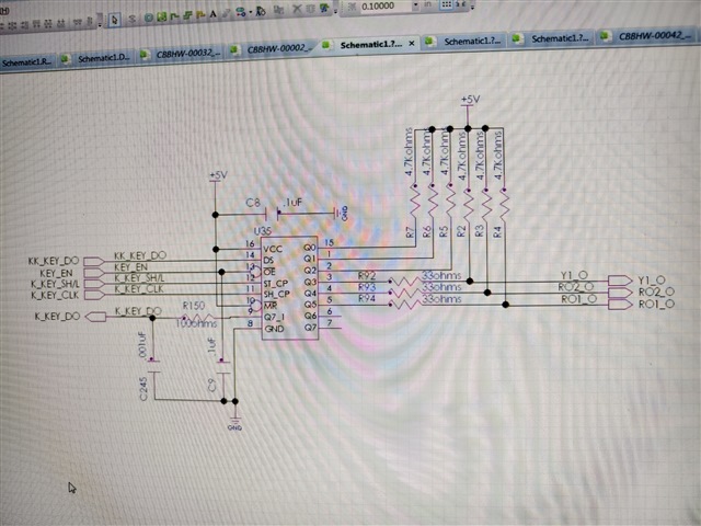
  • This schematic does not show a '595 device.

    10 V exceeds the absolute maximum ratings. Where exactly (which pin) is the voltage injected, and how is the line protected against that?

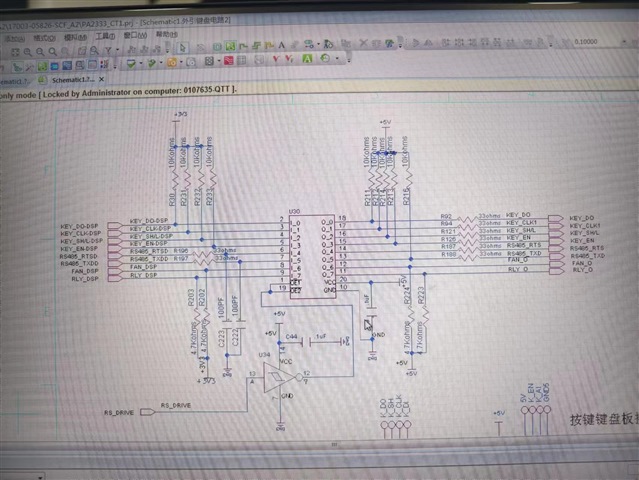
  • Sorry for misunderstanding. The schematic is attached as above. The power supply is 5V as well. The test for EMC is on STO port and not directly connected with SN75HC595, but the phenomenon showed screen was displaying garbled characters. Switching to old batch from our old fab, this abnormal doesn't happen anymore. Can you please give advise on this? Is this because of die size shirked and immunity ability decreased? 

  • Hi Zoe,

    I will have to refer to our design team most likely to see if they have any input into this. 

  • Albert,

    Please kindly informed me once you got internal feedback from design team. Customer is holding back on testing our device for mass production which will had bad impact on our business. Thanks for your help!

  • I did not find "STO" in either schematic.

    The most likely cause is noise coupled into the clock line. Please check the K_KEY_CLK line with an oscilloscope during the EMC test. If this is the problem, you would have to change the board to isolate the clock line from the noise source, or add a low-pass filter to remove high-frequency noise (in this case, to be able to handle slow edges, replace the SN74HC595 with the SN74HCS595 ). Alternatively, change the software to regularly update the display (so that errors are visible only for a short time).

  • Hi Clemens,

    Where and what value should customer add low pass filter? I have already applied HCS595 for customer testing. BTW, when doing EMC test, oscilloscope would be affected thus can not capture the waveform. We need your suggestion on how to modify on the hardware and why HCS technology has better performance on EMC? The STO board is laid as above.

  • The new HC dies are faster, so short spikes might now be interpreted as a valid signal.

    The LPF should be designed to pass through only the highest frequency that is actually used (for digital signals, the analog bandwidth should be about 5…10× the clock frequency).

    HCS, by itself, is not better than HC, but its Schmitt-trigger inputs are able to handle the slow edges generated by the LPF.

  • you mean the RC should be 10times of 150MHz?And on which pin do you suggest to add? Can you provide a pin out reference on this network?Thanks!

  • You want to filter out 150 MHz. What is the frequency of the clock signal that you want to keep?