Because of the Thanksgiving holiday in the U.S., TI E2E™ design support forum responses may be delayed from November 25 through December 2. Thank you for your patience.

This thread has been locked.

If you have a related question, please click the "Ask a related question" button in the top right corner. The newly created question will be automatically linked to this question.

SN74LVC1G123: Delay Jitter

Part Number: SN74LVC1G123

Hi,  what controls the length of the pulse delay for the 74VLC1g123?  And how large is the jitter?

Note that the datasheet only gives tables for the range of the delay.  I am looking for something more specific.   If for example, the delay varies with load, temperature, power supply, etc, then we need some representation of how much it varies with each (c.f. d t_{pd} /d C_L,  d t_{pd}/dT, and d t_{pd}/d V_s etc around some nominal operating condition, c.f., 3pF, 3.3V, 25C).

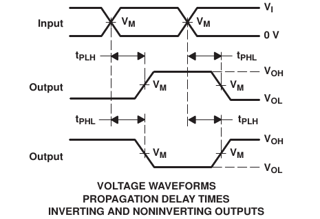
To make it more clear what is being asked,  here is a diagram from the datasheet.  Notice the times indicated on the leading edge of the output,  t_{PHL} and t_{PLH}.   As it says in the footnote, these are the pulse delay times; the time from the leading edge of the input pulse to the leading edge of the output pulse.    Again, this question is not about the pulse length, it is about the pulse delay.
  • I will lead by saying that, for applications requiring precision, you are better off using either a counter or a microcontroller that incorporate a crystal oscillator rather than an MMV. The RC value given by the resistor and capacitor placed on Rx and Cx is what controls the pulse width at the output. There is something called a "K" factor which varies slightly from device to device which needs to be tested for, see below:

    (+) [FAQ] How do you determine the output pulse width and the 'K' value for a monostable multivibrator? - Logic forum - Logic - TI E2E support forums

    K does vary based off of supply, temperature, and the size of the external capacitor and in the datasheet we provide plots for how this K value changes with supply and capacitor size. We do not provide any plots for temperature variance in the datasheet, however the below app note shows that typically you will see ~1% variance in the output pulse width across temperature when the device is isolated. The value will change more when the external capacitor is also exposed to changes in temperature (capacitor values can vary as much as 25% across a temperature range) as this variance will propagate to the width of the output pulse. Please see the SN74LVC1G123 designer's guide below:

    Designing With the SN74LVC1G123 Monostable Multivibrator (Rev. A)

  • Please read more carefully.   I asked about the delay, not the pulse length. 

    Note that I underlined delay, and I explicitly referred to tpd, which the datasheet defines as pulse delay.   I did not ask how long is the pulse.

    Maybe the following will make it more clear.

    Here is a timing diagram from the data sheet, page 10.   Note carefully on the leading edge of the outputs where it indicates t_{PHL} and t_{PLH}.   And see the footnote "G. tPLH and tPHL are the same as tpd."

    Note, again, I am not asking for a lesson in how to set the pulse length for a monostable multivibrator.  I am asking about the pulse delay characteristics of this specific part.

  • I see, sorry for the confusion. All data we have regarding the pulse delay is what is already included in the datasheet. Pulse delay varies with the same values, namely capacitance, temperature, supply voltage, etc. but we've only defined it in terms of supply voltage. We do not spec our devices for jitter or for skew.

  • Okay, thank you.