


Tool/software:
1.TXB0108PWR level conversion chip, the device manual states that "external pull-up or pull-down resistors are not recommended. If it must be used, it is recommended that this value be greater than 50kΩ "(page P17)
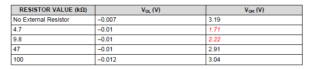
Refer again to the instruction manual "Influence of External Pull-up and pull-down Resistance on TXB", in which the pull-down resistance experiment shows that different pull-down resistance values of the output terminal will have a pull-down effect on the high level of the output terminal (P12,P13).
Question: Does the above indicate that the TXB0108PWR chip can only drive the load with an impedance of more than 50KΩ, and the load with low impedance cannot be driven?
2. The TXB0108PWR chip manual indicates a maximum continuous output current of 50mA (P5 pages)
Question: Under what conditions was this value measured?
Whether this value can indicate that under 3.3V output voltage, 66Ω load can be driven theoretically (3.3V/50mA=66Ω), but under actual low impedance load conditions, the output voltage will be pulled down and it cannot be driven
If the load is to be driven without the output level being pulled down, the 50mA maximum output current shown in the table cannot be obtained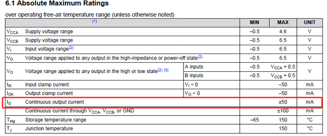
3. The experiment of pull-up resistance in the manual "Influence of External pull-up and pull-down Resistance on TXB" (page P9). The schematic diagram shows that the VCCB pin reaches 3.3V through pull-up resistance.
But the text below describes the B1 output pin by pulling up the resistance to 3.3V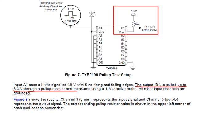
I tested according to the diagram, pulled the VCCB pin up to 3.3V through 10K resistance, VCCA voltage 1.8V, A1 pin input low level 0V, then measured B1 pin voltage is 0
Inconsistent with the test result of VOL=0.977V in the manual (page P11)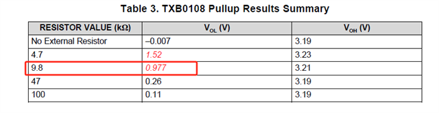
Question: : What are the reasons for the inconsistent test results? Is the instruction manual wrong or the chip itself?

