Tool/software:
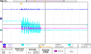
When we tested this IC, output waveform is sometimes oscillated. Would you see attached file?
In our application, pull-up/down register is not same condition.
This is not meet to the datasheet. Is this affected to the oscillation?
Tool/software:
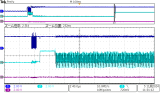
When we tested this IC, output waveform is sometimes oscillated. Would you see attached file?
In our application, pull-up/down register is not same condition.
This is not meet to the datasheet. Is this affected to the oscillation?