This thread has been locked.

If you have a related question, please click the "Ask a related question" button in the top right corner. The newly created question will be automatically linked to this question.

LSF0102: LSF0102

Part Number: LSF0102

Tool/software:

Hello TI folks,

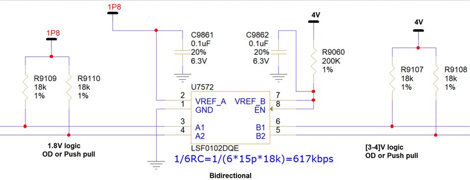
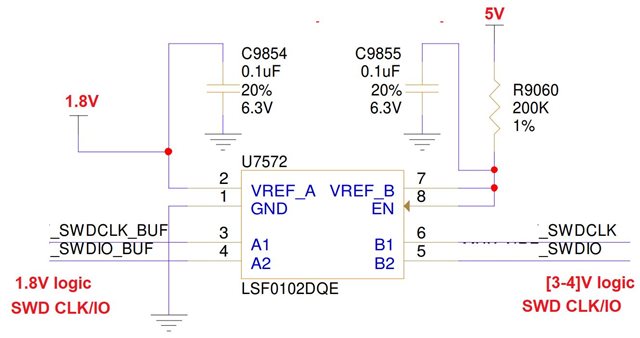
Based on my understanding of the LSF0102, it appears to be a true NMOS pass gate. 
Please let me know your thoughts and comments about the circuit below.
I am utilizing the LSF0102 with VREF_A set to 1.8V and VREF_B set to 5V.
The A-side signal operates at 1.8V logic, while the B-side signal falls within the range of [3-4]V. Either side could be OD (with pull up) or Push Pull.
Given that VREF_B is set to 5V, I believe it will convert the B-side logic in the [3-4]V range to 1.8V on the A-side. Is this interpretation correct?
A-side signals: O.D. with pull up resistors OR Push Pull. 1.8V logic 
B-side signals: O.D. with pull up resistor OR Push Pull in [3-4]V range logic.
Please refer to the attached circuit diagram for further clarification.

Regards,

Reza

  • Correct.

    All output voltages will be clamped at Vref_A; higher output voltages must be generated with pull-up resistors.

  • Thank you Clemens! 

    Reading through more app notes about LSF0102 here is how I updated the circuit 
    VREF_B Side: regardless of whether the IO is configured as Open-Drain (OD) or Push-Pull, a pull-up resistor is required on the VREF_B side.
    VREF_A Side: If the IO is configured as Open-Drain (OD), a pull-up resistor is required on the VREF_A side and if the IO is configured as Push-Pull, no pull-up resistor is required on the VREF_A side.

    Does it make sense to use it as shown below?

    How does LSF0102 manages the buss conflict, for example if both side are driving will it change to OFF state and block the path?


    Regards,

    Reza

  • Hi Reza,

    The team is out today due to US Holiday, and we will get back to you early next week. Thank you for understanding.

    Regards,

    Jack

  • When either side is low, the switch is on and connects the two sides to each other. When one side drives low and one side drives high, then they are connected and will fight against each other. The LSF itself does not care, as long as the short-circuit current does not exceed 128 mA.

  • How about the Pull up resistors?

    VREF_B Side: regardless of whether the IO is configured as Open-Drain (OD) or Push-Pull, a pull-up resistor is required on the VREF_B side.
    VREF_A Side: If the IO is configured as Open-Drain (OD), a pull-up resistor is required on the VREF_A side and if the IO is configured as Push-Pull, no pull-up resistor is required on the VREF_A side
  • I do not know what drivers your other 1.8 V device uses. Anyway, including the pull-ups does not hurt.