This thread has been locked.

If you have a related question, please click the "Ask a related question" button in the top right corner. The newly created question will be automatically linked to this question.

SN74HC165: Q Output Issue

Part Number: SN74HC165

Hi,

My customer used the 74HC165 as in the following SCH.

When using the high value cap for C13, C14, C15 as in the SCH, and add a high signal on the B and D(Other are low level), we found the Q output is wrong as followed:

FIG 1: Green - CLK, Blue - SH/LD, Yellow - QH.

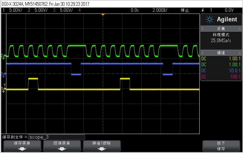
FIG 2:  Yellow- CLK, Blue - D, Green - B.

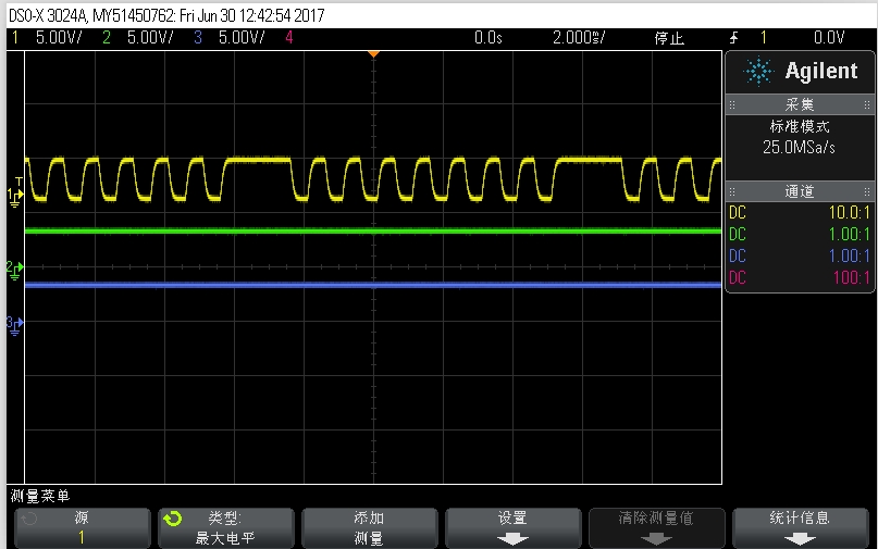
When we remove the C13, C14, C15, the Q output is normal as followed:

What is the root cause for this issue? How about your suggestion? Thanks a lot!

  • Hello,

    I am not sure I understand why there is an RC network connected to the inputs of the SN74HC165.
    If you have a high capacitance on the line, it will cause a slow rising edge.
    A slow rising edge into the input of a standard CMOS device is not good. It can cause additional power consumption, and likely in your case oscillations that are causing multiple triggers at the input of the device.

    It is recommended to have no RC to the input of the SN74HC165 as the inputs are not schmitt trigger inputs.
    If you need to have the RC value for some reason, you will need to add schmitt triggers into the inputs.

    Best,
    Michael