This thread has been locked.

If you have a related question, please click the "Ask a related question" button in the top right corner. The newly created question will be automatically linked to this question.

SN74AUP1G34: SN74AUP1G34

Part Number: SN74AUP1G34

Hi

I have a curious about SN74AUP1G34 's Sink current

please look at the picture 1.

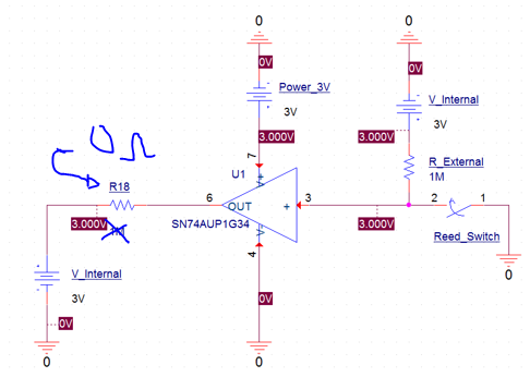
When the buffer input state is low level, the output state is low level.

yes, i know this simple operation. but when the buffer output level is low, How to check 'sink current' flowing buffer output pin (6) ?

When i tested this circuits , i have measured sink current

and the measurement was 60uA.  i don't understand this value

So, i was looked for this buffer datsheet.  but there was no infomation for sink current

why does the sink current have a 60uA ?

And Where can i check the buffer's Input and output Impedance ?

  • Is this an actual circuit, or a simulation? In either case, how exactly did you try to measure the current?
  • i have already tested actual test to measure the sink current. -> using DMM, (serial measurement methode)

    the sink current was clearly 64uA. ( not 60uA )

    but anywhere, nobody knows this infomation. (clearly, even though i have checked the datasheet, there was no info for sink current)

    So, i have a curious this issue

    Could you reply this matter?

    i just wanted to check why this current flows in output pin of buffer

    i guess the buffer's output impedance has a low value,,

  • Hi,
    I'm not sure what you mean by there being no mention of sink current on the datasheet.

    If you check section 7.3 (Recommended Operating Conditions), the output current is clearly defined - sink current is listed as "IOL - Low-level output current".

    Also, if you check section 7.5 (Electrical Characteristics), each output voltage (VOH / VOL) has an associated output current. The sink currents are listed as IOL in the table.

    Are you trying to get a short circuit current from the device? It's possible that you are damaging it during the test since this device isn't designed to operate at short circuit conditions. The maximum output currents listed in the Recommended Operating Conditions table should not be exceeded.
  • thank you for your answering my question

    first,

    last night, i ve already checked that the IoL means the sink current. -> i read the TI basic document (PDF)

    But, When i tested the circuit, i measured that value was 64uA.

    in the datasheet page 7.3,  Vcc =3V , IoL = 4mA (MAX)

    Also, my test circuits condition -> Vcc = 3V,   and actual value IoL = 64uA,  Vo(output voltage) = 0V

    i don't understand this actual IoL value.

    second,

    R18 = 0, -> sink current = 64uA

    * R18 = 13k, -> sink current = 0.2mA -> i think this buffer has some output circuit stage.

    also, it's not matter the short circuits because the internal voltage source limits the source current.

    * i guess the sink current depends on the buffer's internal circuits,,,

     does this buffer has a push-pull output? Could i know the buffer's internal output stage ?

  • "Vcc = 3V,   and actual value IoL = 64uA,  Vo(output voltage) = 0V"

    Is the output pin at 0V but the current is only 64uA? That sounds like an issue with the 3V source, since our device is driving the output to 0V.

    "does this buffer has a push-pull output? Could i know the buffer's internal output stage ?"

    The output stage is a push-pull topology, with some proprietary technology added to reduce power consumption.