Because of the holidays, TI E2E™ design support forum responses will be delayed from Dec. 25 through Jan. 2. Thank you for your patience.

This thread has been locked.

If you have a related question, please click the "Ask a related question" button in the top right corner. The newly created question will be automatically linked to this question.

SN74GTL1655: Output ringing in the falling edge

Part Number: SN74GTL1655

Hi team,

My customer use the part in the switch. And below is the diagram.

The signal is from the A port to B port.

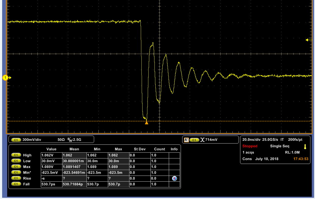
 And they find the B port signal has a ringing in the falling edge.(show as below).

So please help to answer below questions:

1. What may be the cause for the ringing?

2. Customer tried to increase the 0 ohm resister, but it seems a little improvement, not much. So do you have any suggestion for eliminating the ringing?

Lacey

Thanks a lot!

  • Hi Lacey,
    The B port of this device has extremely high drive strength, and as such will have ringing into light or inductive loads. There are two ways to reduce it that I know of - one is to add a series resistor, and the other is to add load capacitance.
  • Hi Emrys,
    For the cap load, you mean connect a cap between the C and the GND or the B and the GND(in the diagram)?
    Also, please help to recommend the resistor and cap value for the ringing issue?

    Lacey
    Thanks a lot!
  • Hi Emrys,
    Customer say they can increase the series resistor.
    But they also want to know, if the 75 ohm pull up resistor is proper, can they increase the pull up resistor.
    In addition, if the 75 ohm pull up resistor will affect the ringing. If so, do you have the recommend value for the pull up resistor?

    Lacey
    Thanks a lot
  • Hi Emrys,

    My customer has tried using the 50ohm series and 1k pull up resistor in the circuit I have show at the beginning.

    But my customer worried if the 1k pull up resistor will affect the B port signal.

    So my customer want us to help to evaluate if the solution will affect the function of our unit.

    Lacey

    Thanks a lot!

  • Do you have any additional information about the circuit? From what you've said, it seems that there's more going on that you are sharing. What kind of wire is used to connect these devices? How much inductance does it have per unit length? My guess is a lot....
  • Hey Lacey,

    I thought you might like to see my simulation showing what might be going on. Here I have 3 identical output drivers with 3 different loads. The first two have transmission lines as part of the load, and the third has the TL removed.

    The key thing to take away from this is that increasing the inductance on the line will increase ringing. A 50 ohm transmission line typically has 100pF and 250nH per meter (the ratio is controlled by the equation Zo = sqrt(L/C) ).  I suspect something like this is happening in your customer's circuit.

    I also included my Tina-TI simulation file if you want to show them directly.

    TL_ringing.TSC

  • Hi Emrys,

    Thanks a lot for your effort!!

    Now, customer tried the change the value as below:

    Using the value, customer can solve the vibration problem.

    But now customer's concern is that because the port B is OD port, they need to put a pull up resistor. In their current circuit, they connect the pull up resistor on the left side of the series resistor. 

    1. Will it cause other problem? such as affect the function of our part?

    2. What's the recommend value for the pull up resistor according their current circuit?

    Lacey

    Thanks a lot!

  • It will depend on the load and the operating frequency. Since they are using a 50 ohm damping resistor, I would recommend at least 10x that for the pull-up (500 ohm). If possible, I would recommend a 10kohm, but that might result in too slow of a signal for the CPU. 1k is probably a good choice.
  • Hi Emrys,
    Thanks for your reply.
    I have confirmed that the signal is the DC signal. So maybe the most concerned is the load of the CPU pin.


    Lacey
    Thanks a lot!