This thread has been locked.

If you have a related question, please click the "Ask a related question" button in the top right corner. The newly created question will be automatically linked to this question.

SN74LS279A: sn74ls279A

Part Number: SN74LS279A
Other Parts Discussed in Thread: TINA-TI

Hello I was wondering the following,

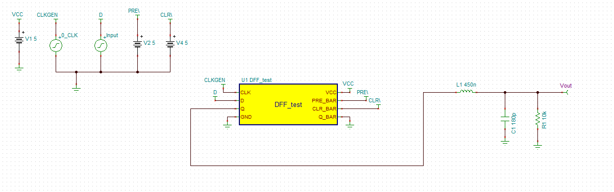
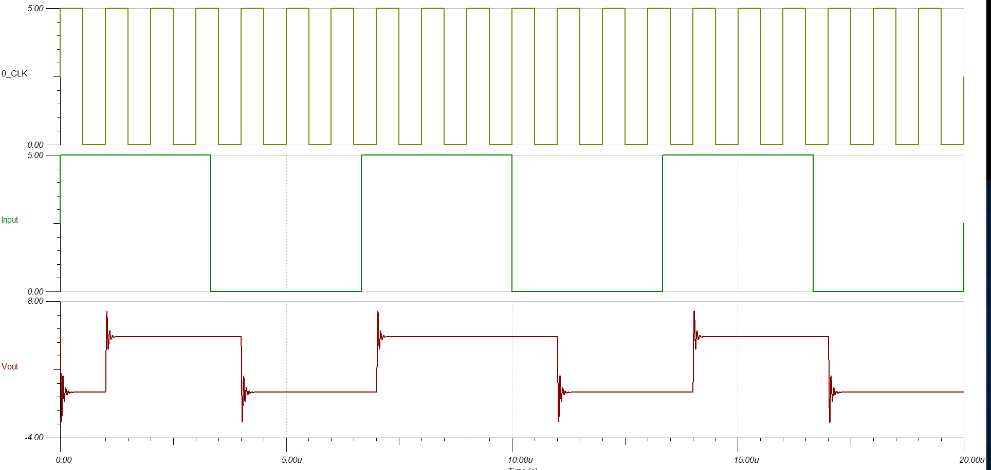
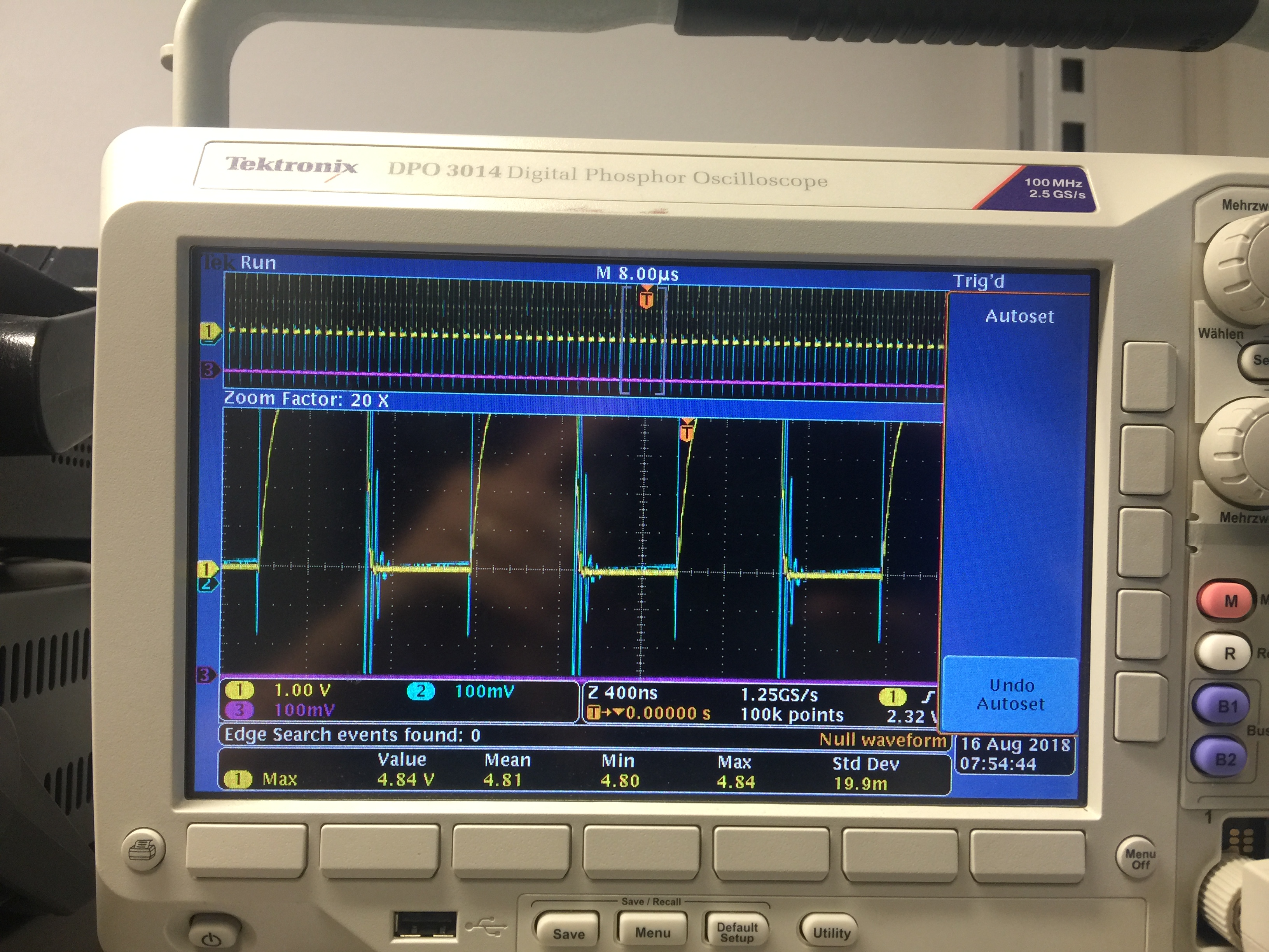
if the SN74LS249 Inverted Flipflop can drive a 50Ohm bnc cable which is terminated on the other side with 10K.

which bnc driver should I include if not?

the sn74ls279a is it used for 5V or 7V?

Best

Bastiaan

  • Hi Bastiaan,

    Logic isn't typically used for transmission lines. Further more, using a 50 Ohm bnc cable with a 10k load will cause ringing due to transmission line effects.
    Can you specify what frequency you are trying to operate at?
    If you would like I can create a TINA-TI model for you showing a flip flop with a 50 Ohm transmission line with a 10k load. You will be able to see the ringing that is caused.

    Thanks!
    - Karan
  • Thanks for the fast reply the max speed would be at 1KHz.

    Sure cool you could  do this ? Thanks in advance

  • Bastiaan,

    I can make the model for you, but please allow me a few days to be able to do this. In the mean time here is a post that discusses the impact of a transmission line.
    e2e.ti.com/.../717149
    If you look at the response you will see a sample model that shows a 50 Ohm transmission line with a 10kOhm termination like for your case.

    How long is your transmission line and would this ringing on the output be fine for your application? Since the signal will be switching so frequently, it will cause large amounts of oscillations on the transmission line. You might want to think about some way to possibly match the output and input impedance.

    Thanks!
    - Karan
  • sure in the mean time, I am looking into a model from LTspice which can be used for transmission lines 50 ohm cable (LTC6268), allthough I cannot see a reflection during the simulation, I changed the rise and fall time of the 5V and frequency over a period. I only see spikes on the edges because of the parasitic inductances in the cable.

    a 48.7Ohm resistor will do the job, other solutions that can be presented is a Logic family with a 4 channel output each 200 Ohm in parallel, or a TC4427 28 for harder switching. still however I would like to see your simulation:) many thanks for your research on your side.
  • Hi I worked with two simulations programs to check the validity of the circuit.

    clock 1 1m 500u

    clock 2 1u 500n

    clock 3 200m 100m

    for some reason I am having a reflection on the line also with the  capacitor in series in the bnc line. the IRF510 is just an example for the TC4427a. could you check this please with tina ti?

    best Bastiaan Pierik

  • Bastiaan,

    So a spice simulation like LTspice or TINA will not be able to accurately model the reflections from a transmission line. You need to use software like microwave office.

    I created a TINA model with a D Flip Flop as I do not have a model for the SR latch as of this moment.  Ff your transmission line is RG-58, a 50 ohm line with ~100pF per meter, then you'd expect to have about 180pF of parasitic capacitance and 450nH of parasitic inductance in a 6 foot (1.8m) length Z_0 = sqrt(L/C).

    My recommendation is that you make your model using another software or actually develop and test it so that you can see what it would actually do.
    SPICE modeling tools are not very accurate for transmission lines.

    Thanks!

    - Karan

  • thanks for the reply:) I was annoyed by the simulation programs and thanks for the pointing out the Zo=sqrt(L/C) thing. I understand it now, it resembles 50 Ohm.

    so it becomes logical to terminate it with a similar resistance to drain the parasitics.

    I used a 74LS04 at a 1MHz signal both passive probes were deskewed beforehand at 1KHz.

    2 cables I used are RG58 2x 1meter with a BNC T connector inbetween with at the end a 10K termination i measured with a 1Mohm on the 10K termination.

    the yellow signal is a 49.9 Ohm output resistance behind the 74LS04

    the blue signal is without the 49.9 Ohm.

    at 1MHz signal it looks like this.

    at 1KHz signal it looks like this.