Other Parts Discussed in Thread: SN74LV4T125
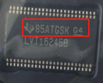
There were two failures in our company's nearly 200 sets of finished products,
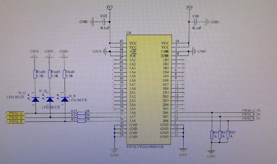
one of which was below 10 ohms of the Pin20 pair of ground impedance as shown in the figure,
and one of which was below 10 ohms of the PIN22 pair of ground impedance as shown in the figure.
The internal breakdown was suspected.Is there any problem with my schematic diagram? Could you please check it for me?
In addition, PWM terminal input has any good Suggestions, or reference circuit.?
thank you!


