This thread has been locked.

If you have a related question, please click the "Ask a related question" button in the top right corner. The newly created question will be automatically linked to this question.

My SN74LS112AN ICs aren't as independant as the datasheet says they are.

The task in my lab said to build a 2-bit binary up-counter and provided the following schematic:

            So I built that circuit on a breadboard and wired Pin 1 and 13 together in parallel. The circuit would only increment the output from Pin 5(Q0). After some time of building, rebuilding, checking voltages, etc., I isolated the chips and tested everything independently. Both FFs worked as expected. Then I wired the above circuit bit by bit to see when something went wrong. I accidentally forgot to connect Pin 13 to the CLK input and suddenly the circuit worked. I checked all 5 chips I have and 2 locations on the breadboard. None of my chips function in the circuit if both Pin 13 and Pin 1 receive the same signal. Which doesn't sound right at all. I modeled the above diagram in a simulation program and it works fine and the datasheet says those pins are independent. There is one other student who had the exact same issues I did. Everyone else got theirs to work.

So did we get a bad lot, or is there something I'm not doing correctly? I've already turned the lab in, so I'm not looking for any answers to that end. I'm just generally curious as to why the first diagram doesn't work. I appreciate any insight you guys can give!

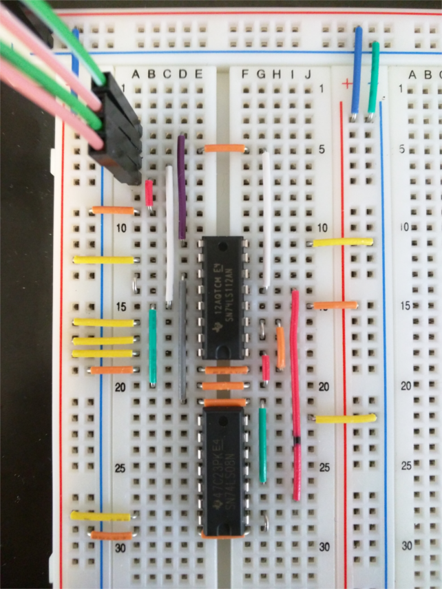
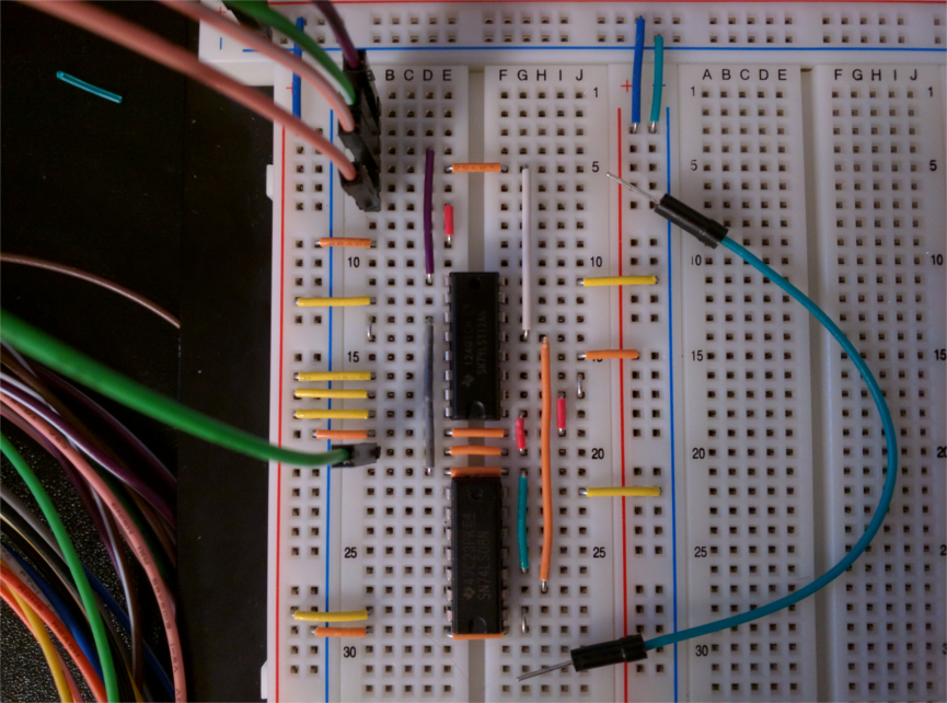
Here are the circuits I built in case it helps.

Circuit as interpreted from the given diagram. The black spot is just a marking and the leftmost blue bus bar was used to send the Count signal to the lower 74LS08 chip and the 74LS112AN chip.

Here are the wire designations:

Pink: Count

Green: Clock

Pink/White: Q0 (output)

Green/White: Q1 (output)

And here is the one that works. The pictured loose jumper wire is the only one that I could use to connect header pin 2 to row 20. No other jumper would work whatsoever, so I moved the input wire down instead. Pin 13 is no longer receiving a clock signal.

  • How is the clock signal generated? With a mechanical button?

    Were you ever taught about decoupling capacitors?
  • The clock signal was generated by Digilent's WaveForms software and their Analog Digital Discovery Kit. In the software, a toggle switch was used to manually send an on/off signal to the CLK inputs on the ICs. This album shows the different combinations of connections involving Pin 13 and Pin1 and whether or not the circuit functions as expected.

    And no, I have not learned about those yet. I googled it though, and looks like they would be placed between the IC and it's power source to protect against power dips during operation of both FFs at once. But I could be wrong on that.

  • Hi Hunter ,

    you are right about the caps between power supply and pins . They are used to reject the noise on supply rails which could cause malfunctioning of the chip by false triggering of the output . Also, to temporarily sustain the voltage during a power surge from the device . Different caps could be used to reject different noise frequencies and they need to be as close as possible to the chip.

    I have attached an app note here. which should be beneficial .

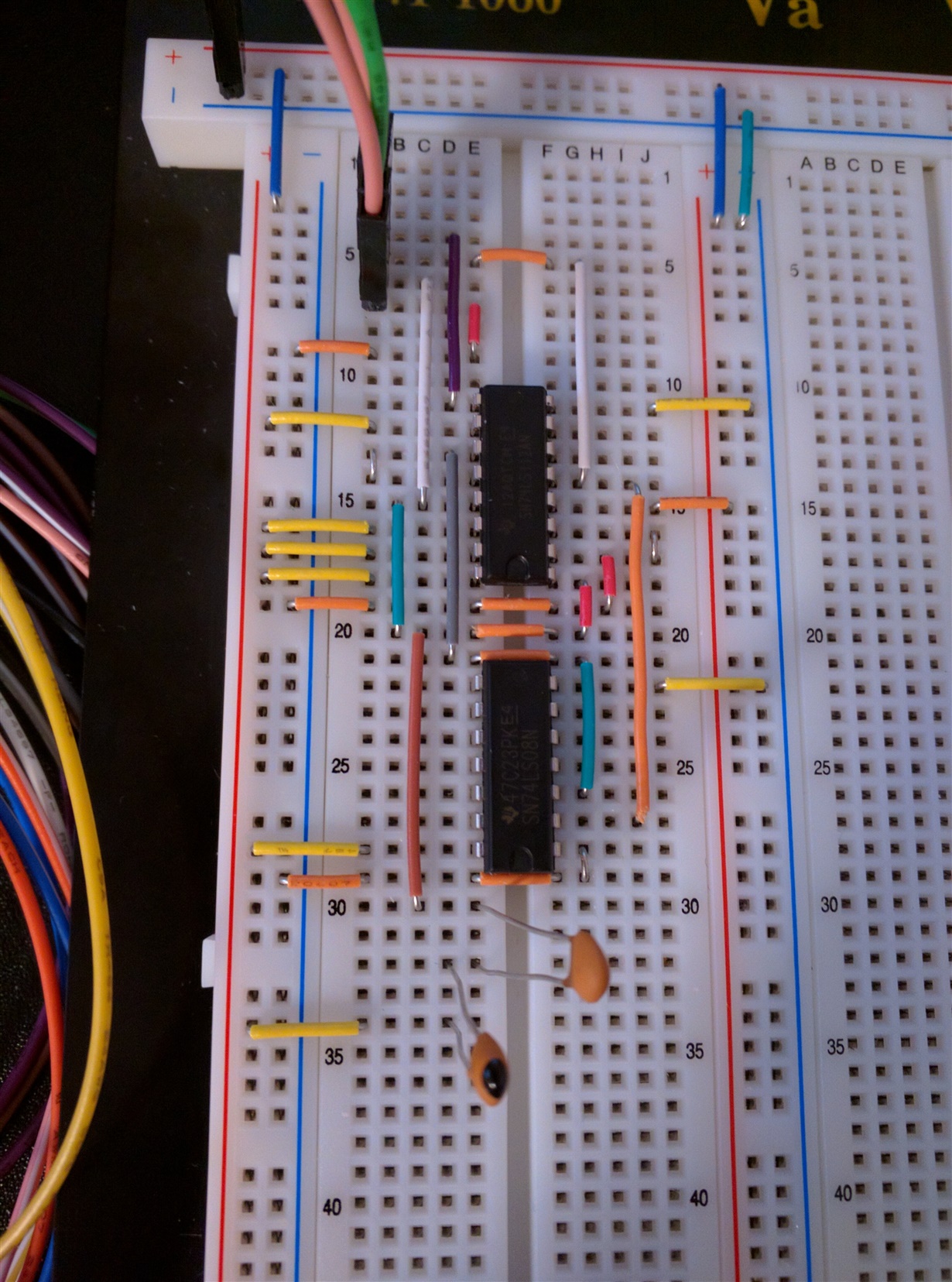
  • Tl;Dr: I accidentally built a capacitor signal filter. If the capacitors are connected directly inline, a parallel capacitance of 200(pF) will filter the signal properly. I wanted to clean up the look a bit so I moved it and found that a series capacitance of 28(pF) will work.

            I tried a few capacitors at the power source and the circuit would cease all output each time. So I decided to set up a pulse wave, actual clock signal, so that I could use a voltmeter to poke around during tests to see what was happening. To my surprise, the circuit worked perfectly. So I disconnected the oscilloscope and tested it again. The circuit went back to counting to 1 and back to 0. So I hooked up the oscilloscope again and the circuit worked again. Then I hooked up two random wires that do not map to any function, one to ground, an one to the branch the CLK signal is on and the circuit worked properly. Then I tried placing a jumper straight to ground, and as expected, it just shorted the CLK signal. That's when I started thinking about decoupling capacitors.

              I figured a decoupling capacitor could be used to reject noise from more than just power sources so I used my multimeter to see if there was a measurable capacitance between two wires on my ADK. Turns out, there is a 200(pF) capacitance between the wires. It just so happens that I have two 100(pF) capacitors so I stuck them in the positive bus and into the CLK branch, in parallel. Boom, the circuit worked. I wanted things a bit more spread out so I moved the capacitors to where they are in the picture. The move caused the equivalent capacitance to change (I think that's the reason) so I had to play with what I had to fix it. I found that a series equivalent capacitance of ~28(pF) would filter out whatever the ADK doing.

    Thank you both for the help! Bonus points for teaching me something. 

  • A decoupling capacitor is not between a chip and the power supply; it's parallel to the chip, between VCC and GND. And the most common value would be 100 nF.

  • Ooooooh, ok. I tried that, connecting both capacitors between the Vcc and GND pins of the chip and the circuit still didn't work. What did I make above? When I thought about it this morning, it didn't make any sense that those capacitors when hooked into the Vcc rail. I used an oscilloscope to check the signal for CLK and there were no anomalous readings. The high voltage was right were it should be. However, using a voltmeter to check the voltage of the CLK signal, with no caps in the network, causes the circuit to work. Are the caps were acting as a filter for the CLK signal?

    Here is an album of Cap configurations that work. These are the only configurations that caused the circuit to work (aside from the pic above.
    http://imgur.com/a/ZeQnr