This thread has been locked.

If you have a related question, please click the "Ask a related question" button in the top right corner. The newly created question will be automatically linked to this question.

SN74LVC1G123: rising/falling edge detector reliability problem

Part Number: SN74LVC1G123
Other Parts Discussed in Thread: CD74HC4538, CD74HCT4538, CD54HC4538, CD54HCT4538

Good day

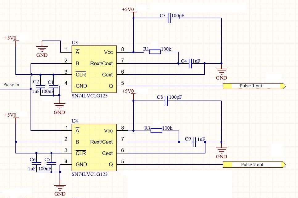
I am currently fault finding an edge detector circuit. It is installed on a site that is experiencing frequent power failures. Unfortunately, the power failures are out of our control. The result for us is that sometimes the below circuit gets "stuck". 

What I mean by this is that the relay which is triggered by this circuit fails to trigger. Once the failure mode is created, then there is no reliable way to get the circuit to operate normally. Power cycling does not clear the fault.

I managed to create the fault once in the workshop with the following:

- The fault seemed to occur after a power fault in our building/lab (coincidentally). 

- The 5V is supplied by a bench power supply. 

- The "pulse in" goes high for one second then low for one second.

- The "Pulse 1 out" switches a relay on, "Pulse 2 out" switches the relay off.

- During the failure I managed to measure the following:

- Pulse 2 out stuck at 5 VDC

- 2.3 VDC measured across C9.

- Pulse 1 out triggering as normal.

- 5 VDC measured across C4.

- Power was removed

- The circuit was left powered down overnight.

- In the morning, I connected power and measured the same failure.

- The fault resolved itself after I was in a meeting for an hour. I unfortunately did not leave the circuit powered.

 - The fault has not since returned.

My question is: Is there any improvement I can make to this circuit to make it resistant to this type of failure?

Also, is there a device more suited to this application that is less susceptible to start up and switch off transients?

Any suggestions are appreciated. 

  • Hi Wesley,
    I have notified the appropriate applications engineer to respond to you. Can you also provide the circuit for the relays/what is beyond "Pulse n out"?
  • Hi Emrys
    Thanks for the reply.

    The "Pulse n out" is connected directly to Radiall R570.432.100 coaxial switch terminal E1 and E2 respectively. The current draw on E1 and E2 are given as 800 uA at 5V in the datasheet.
  • Hey Wesley,
    It seems that Shreyas is out today, so I'll take a stab at this.

    My first guess would be that this is being caused by inductive kick from the relay. Can you add external clamp diodes (schottky) to keep the Q output from being driven above Vcc or below ground?

    Excessive current through the internal clamp diodes can cause latch-up, which I believe is the issue you are having.
  • Hi Emrys

    Sorry for the long delay in reply. We decided to go with a completely different design based on the Atmel Tiny26 to generate the pulses to switch the relay.

    I am still interested in finding the root cause of the failure.

    With reference to your first guess; normally that would be the most likely cause.

    In my case, the input to the relay is a TTL control, which is connected to a separate 12 VDC supply. 

    The actual current draw from the Q output into the TTL control of the relay is about 5 uA.

    Unfortunately it is difficult to see if the clamping diodes will make a difference because the problem is very difficult to reproduce. We have only been able to recreate the fault once in the lab with about 3 weeks of testing.

    The fault occurred after the main power to the test bench failed.

    Is it possible that the latch-up problem could be due to the large capacitor on the Rext/Cext pin to ground?

    I read on another product datasheet that a latch up condition could be created if the Vcc drops off very quickly and the Rext/Cext capacitor stores enough charge to be above the Vcc voltage level.

    I suppose the solution in this case would be to put a larger capacitor across Vcc and GND.

    I would appreciate your further thoughts on the above


  • We do typically recommend adding a series resistance to the capacitor for anything larger than 0.1uF of ~51Ω. This is just to limit the discharge current through the MMV's internal circuitry.

    Since the failure is happening with a system level event (ie power failure), it's likely that there's more going on than just this. It would be interesting to monitor the power rail, inputs and outputs of the SN74LVC1G123 during such a failure.

  • Hi Emrys
    Thanks for the information. I actually did see the recommendation for the 51Ω resistor for other devices but I could not find anything in the datasheet that it applies specifically to our used device. Our capacitor used was 1uF, so I can definitely see a place to improve the design.

    Can you double check from you side? Maybe I just missed it.

    The other datasheet i am referring to above is SCHS123E (for CD54HC4538, CD74HC4538, CD54HCT4538, CD74HCT4538 page 10 specifically)

    If it is the case, then maybe you can add this to the datasheet to prevent confusion in future.

    With reference to the power rails, it was running directly off a bench power supply. The circuit was drawing 6mA. I did not see a rise in current during the fault and the failure seemed to be directly related to pin 7 of U4 (shown above). I did not put a scope on the voltage rails during the failure.

    While the failure mode was present, I did measure the input and output pins with no pulses applied. I compared the levels to the working device. The only difference i found was that the voltage measured at pin 7 of U4 to ground was not as expected (2.3VDC) and pin 5 of U4 was constant 5VDC.

    Kind regards,

    Wesley
  • It's not explicitly stated in the datasheet, however it is good practice. I haven't ever seen large capacitors cause a problem - and it sounds like this issue was very rare and is probably specific to the system.
  • Hi Emrys

    Thanks for the information. It looks like we won't be able to get the root cause without investing more resources.

    I feel that I have learnt about the device during this process so I feel that the design can be improved when we use it again.

    Can we close this discussion?

  • Thanks for visiting the forums - and good luck with the rest of your design!