This thread has been locked.

If you have a related question, please click the "Ask a related question" button in the top right corner. The newly created question will be automatically linked to this question.

CD4046B: Use PLL CD4046B and frequency divider CD4040B to design a 60Hz frequency tracker

Part Number: CD4046B
Other Parts Discussed in Thread: CD4040B, , TINA-TI, CD74HC4046A, SN74LV4046A

Hello,

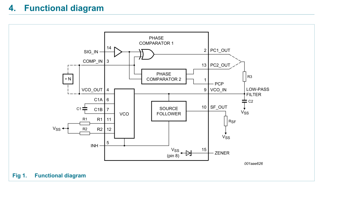
I would like to use PLL CD4046B and  frequency divider CD4040B to design a 60Hz frequency locker.

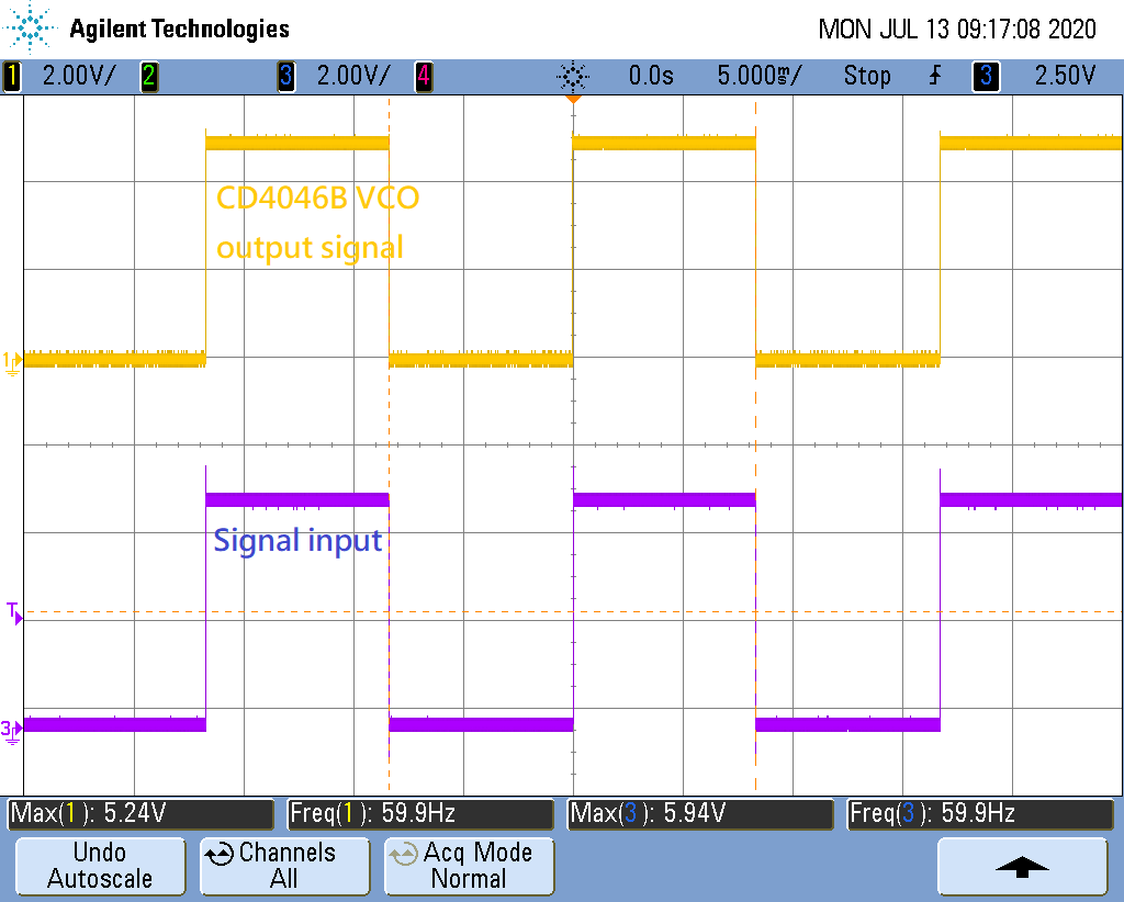
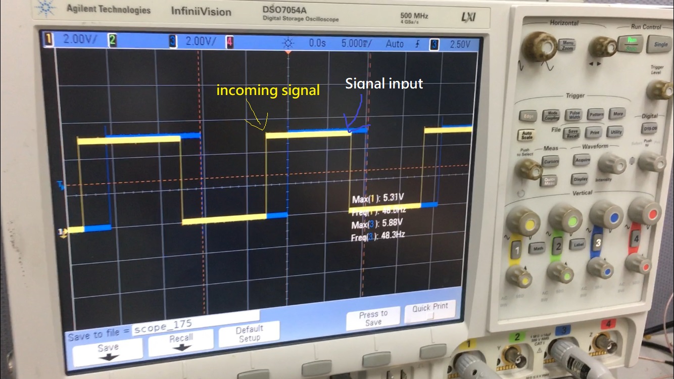
The circuit target is to lock a 60Hz signal.

How could I start?

Please anyone to figure it out with me. 

Thanks in advance.

Assume that the VDD is 5VDC and only use the phase comparator 1, the frequency divider CD4040B can be divided by 1024 or 2048.

1. How to determine the VCO output frequency to achieve my target? 

2. How to determine the value of R1, R2, C1, and low pass filter R3, C2?

3. Attached is the simulation file and the tool is LTSpice.

The detail can be find in HEF4046B datasheet.

HEF4046B.pdf

PLL Test.zip

  • Note that the function block diagram and components of PLL as attached.

  • Hi,

    Our datasheets should provide some guidance on setting up each device. You displayed a datasheet from another manufacturer, I can't help with that device. Have you examined our devices datasheet? Unfortunately, I also can't open your LTspice simulation. I'd recommend TINA-TI to run your simulations if you want me to be able to open them. 

  • Try looking at the SN74LV4046A and CD74HC4046A datasheets.

  • Hello,

    Were you able to get your system designed?

    Building a PLL for 60 Hz should be relatively easy with the components you have selected.  The diagram you provided is a good starting point.

    My recommendation would be to first very carefully read the entire datasheet for both devices. I know that this is tedious, but these are complex devices and there's a _ton_ of useful info in the datasheets. The additional datasheets others have provided are also useful resources, as the '4046 function is pretty much the same for any logic family or manufacturer.

    First you need to select your supply voltage and VCO operating frequency, which is going to be related to your desired lock frequency and the size of your counter. I'm going to assume 5V since that's a very common operating voltage and might allow you to select other parts that are more modern later (CD4k logic is quite old and optimized for 15V operation, which doesn't work with any other logic family).

    The VCO lists a minimum 'max operating frequency' of 300 kHz (0.3 MHz) at 5 V with a 10kohm R1. This spec can often be confusing -- the meaning is that the output frequency will _definitely_ be able to hit 300 kHz, however beyond that we cannot guarantee that the oscillator will work -- the typical max at 5V is 600 kHz.

    Looking at figure 4 in the datasheet, you can see the RC values required at 5V to set the VCO to 60 Hz directly:

    Based on this, I don't think you really need the counter.  You _could_ set the frequency up to ~120 kHz, and then divide it back down again to 60 Hz, but why do that when you can just configure the CD4046B directly to operate at 60 Hz?

    You can set the timing values as given above - R1 = 1 Mohm, C1 ~= 0.08uF (80nF).  Typically prototyping is the best way to check out these circuits -- just hook them up with 'close' values and then adjust as needed to get your final frequency range on the bench. You can also add an offset with R2 = 1 Mohm to try to narrow the operating frequency range, but most likely that won't be required and you can just leave R2 as open circuit.

    The biggest problem with this particular application is that the 60 Hz signal is very slow, so your response time of the PLL will also be relatively slow. It probably won't matter though, since I'm guessing you are trying to match phase with a power signal, and those don't have fast fluctations in phase or frequency.

    I would recommend using 100kohm and 10uF for your low pass filter out of the phase comparator of your choice (PC1 will give you a 90 degree phase difference, PC2 is going to be phase matched). These values give a cutoff frequency of ~0.2 Hz, which will be relatively slow to respond, but will stabilize the VCO well.

  • Hello sir,

    Thanks for your information.

    You are right that I am trying to sync a ac power line signal which is 50Hz or 60Hz.

    According to CD4046B datasheet, figure 4, the R1 supposed to be 100k ohm but not 1Mohm at center frequency 60Hz, 5V.

    Could you please check the recommend value of R1?

    I am trying to do some simulation by TINA.

    But there is no avaliable spice model of CD4046 on TINA or TI website.

    So I do some search online and have a CD4046 model which is consist of macro.

    I am not sure if this macro is avaliable for CD4046.

    Anyways, I did some simulate, the attached is the TSC file. Please take a look.

    I did a transient analysis and use oscilloscope function to monitor the VCO output signal.

    But the signal do not lock at 60Hz.

    Could you please advise how to modify my schematic?

    By the way, I purchased some CD4046 ICs, I would do real test on this issue, will keep update this thread.

    Thank you.

    CD4046_PLL.TSC

    SK.

  • Hey SK,

    Yeah these older images are a little harder to pinpoint the right curve, but yes the line you've intersected is for 100 Kohm R1.

    Unfortunately, due to the age of this device and acquiring it from Harris, we wont have simulation model for it. Since it was acquired through a different source I'm not sure if I will be able to help debug the simulation itself since it could just be an inherent model issue and there really is no way of me verifying. For this reason, I will be more focused on your real world measurement results. If those don't turn out the way as expected, I'll be happy to help support the debug process in anyway i can.

  • Hi Dylan,

    The circuit works.

    In my experiment, I choose R1=100Kohm, C1=100nF and keep R2 floating. The maximum frequency could be locked is around 140Hz.

    The low pass filter, I reference to the application report of TI 'SCHA002A', see the attachment, in which section 4.2, describe how to do a Frequency Synthesizer.

    Figure 12. shows a low pass filter consists of 2 resistors and 1 capacitor.

    The LPF for this application is a two-pole, tag-lead filter that enables faster locking for step changes in frequency.

    I choose the low pass filter of R3=1Mohm, C2=2.2uF and R4=220kohm.

    One more question, what is the key point of selecting LPF RC values?

    Thanks.

    SK.

    scha002a.pdf

  • Hello,

    Sorry about my previous error - I was in a bit of a hurry when I wrote that and didn't double check. I'm glad you got the circuit working!

    The key selection criteria for the low pass filter are going to be cutoff frequency and response time. It would be ideal to have a constant voltage on the input of the VCO to prevent variation in the oscillator's output - and to have it respond instantly, however the output of the phase comparator is a square wave, which has a broad spectrum of frequency content. The low pass filter is designed to reduce the signal to only the DC element.

    I would typically recommend choosing a cutoff frequency ~2 orders of magnitude less than the operating frequency (0.6 Hz in this case) to maximize response time while minimizing variations in the output.

    By selecting a higher order filter, you can improve response time and more precisely select the cutoff frequency.


    There are entire books written on filters -- I would recommend trying a simple RC filter first, then if that doesn't meet your needs, look into higher order filters. You can always give a few active filter designs a try - there are many websites out there that will do all the calculations for you.

  • Hi Sk,

    The low pass filter values will impact the capture range which can be seen on page 3-125 of the CD4046B. The note also provides some literature that goes into great detail on the control theory behind it. 

    This capture range will be less than or equal to the lock range and will determine the range of frequencies the PLL can lock to if initially out of lock. 

    Also, I'm glad to see the real world testing is working as planned.

  • Thanks for your support.

    Note that issue has been solved.